Chapter 3: Installation
3.1.2 Rack mount
Note: The module switches are not accessible once it is inserted into the rack, therefore, check all settings before insertion.
1Place the rack securing plate (available as a separate kit) onto the front of the module and secure it with the two countersunk screws.
2Orient the ServSwitch Wizard DVI/USB SRX module on its side so that its labeled face is the correct way up.
3Slide the module into the required rack position. The rectangular
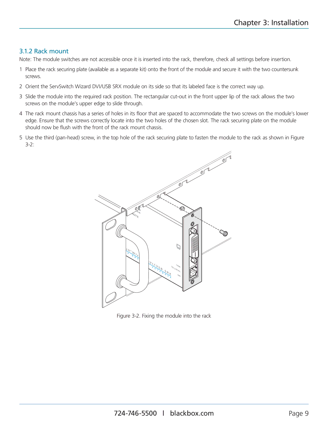
4The rack mount chassis has a series of holes in its floor that are spaced to accommodate the two screws on the module’s lower edge. Ensure that the screws correctly locate into the two holes of the chosen slot. The rack securing plate on the module should now be flush with the front of the rack mount chassis.
5Use the third
TE
| S |
|
| e |
|
| r |
|
| v |
|
| S |
|
| B | L |
| ||
|
|
i |
| |
| t |
|
A | c | |
| C | K |
|
| |
™
B
i |
| ||
O | z | a | |
X | |||
|
| ||
K | V |
|
| M | |
|
|
I |
|
|
|
|
| |
E | / |
|
|
|
|
|
X |
|
|
|
|
| |
| T |
|
|
|
| |
|
| E |
|
|
| |
|
|
| N |
|
| |
|
|
|
| D |
| |
|
|
|
|
| E | |
|
|
|
|
|
| |
TO
R
LINK LOCAL
ON
Figure 3-2. Fixing the module into the rack
Page 9 |