CODE OPERATED SWITCH II
3. Installation
3.1. Introduction
In addition to this manual, your Switch package should contain one standard switch unit and a wallmounted power supply. After you’ve unpacked the Switch, take a few minutes to look through this manual. You will need a screwdriver large enough to remove the case screws, and a small screwdriver or other edged tool for setting DIP switches. Also, you might want to refer to the manuals of the devices you plan to connect to the
Installing the
switches for the internal options of the COS II. Then, you’ll specify DTE or DCE for each port by setting shunt jumpers. Finally, you’ll cable the Switch to your devices and connect power to the
COS II.
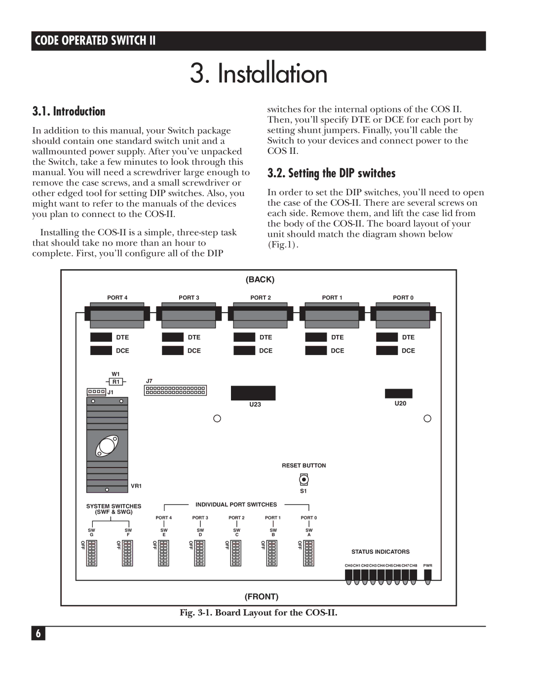
3.2. Setting the DIP switches
In order to set the DIP switches, you’ll need to open the case of the
(BACK)
| PORT 4 |
|
|
| PORT 3 |
|
|
| PORT 2 |
|
|
| PORT 1 |
|
|
|
|
|
|
|
|
|
|
|
|
|
|
|
|
|
|
|
|
|
|
|
|
|
|
|
|
|
|
|
|
|
|
|
|
|
|
|
|
|
|
|
|
|
|
|
|
|
|
|
|
|
|
|
|
|
|
|
|
|
PORT 0
DTE
DCE
W1 |
|
R1 | J7 |
![]()
![]()
![]()
![]()
![]()
![]()
![]()
![]()
![]()
![]() J1
J1
VR1
SYSTEM SWITCHES
(SWF & SWG)
PORT 4
DTE |
| DTE |
|
|
|
DCE |
| DCE |
U23
RESET BUTTON
S1
INDIVIDUAL PORT SWITCHES
PORT 3 | PORT 2 | PORT 1 | PORT 0 |
DTE
DCE
DTE
DCE
U20
| SW | SW | SW | SW |
| SW | |||
| G | F | E | D |
| C | |||
OFF |
| OFF |
| OFF |
| OFF |
| OFF |
|
|
|
|
|
| |||||
|
|
|
|
|
|
|
|
|
|
SW
B
OFF![]()
![]()
SW
A OFF ![]()
![]()
![]()
![]()
![]()
STATUS INDICATORS
CH0 CH1 CH2 CH3 CH4 CH5 CH6 CH7 CH8 PWR
(FRONT)
Fig. 3-1. Board Layout for the COS-II.
6