Automatic Timeout
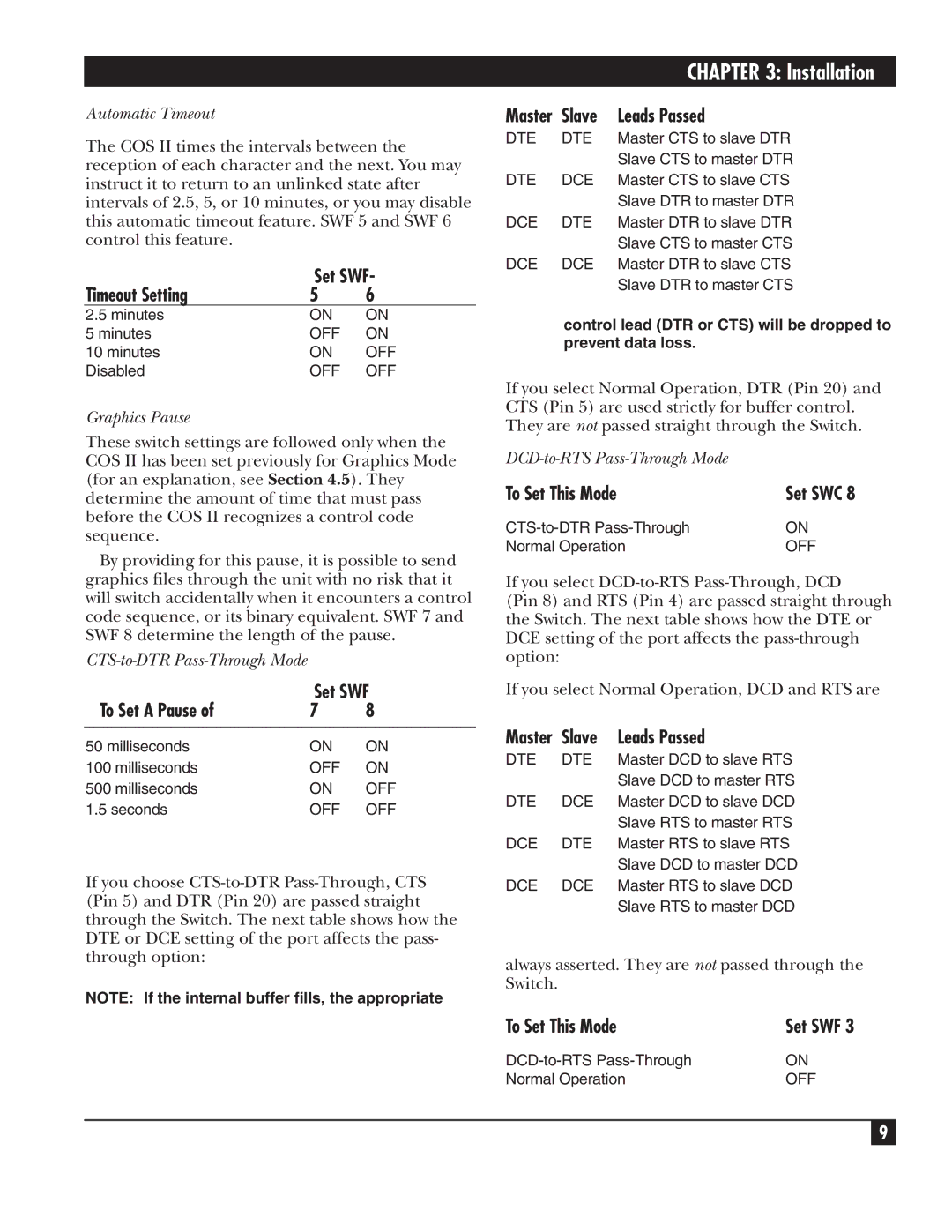
The COS II times the intervals between the reception of each character and the next. You may instruct it to return to an unlinked state after intervals of 2.5, 5, or 10 minutes, or you may disable this automatic timeout feature. SWF 5 and SWF 6 control this feature.
| Set SWF- | |
Timeout Setting | 5 | 6 |
2.5 minutes | ON | ON |
5 minutes | OFF | ON |
10 minutes | ON | OFF |
Disabled | OFF | OFF |
Graphics Pause
These switch settings are followed only when the COS II has been set previously for Graphics Mode (for an explanation, see Section 4.5). They determine the amount of time that must pass before the COS II recognizes a control code sequence.
By providing for this pause, it is possible to send graphics files through the unit with no risk that it will switch accidentally when it encounters a control code sequence, or its binary equivalent. SWF 7 and SWF 8 determine the length of the pause.
| Set SWF | |
To Set A Pause of | 7 | 8 |
|
|
|
50 milliseconds | ON | ON |
100 milliseconds | OFF | ON |
500 milliseconds | ON | OFF |
1.5 seconds | OFF | OFF |
If you choose
NOTE: If the internal buffer fills, the appropriate
|
| CHAPTER 3: Installation |
Master | Slave | Leads Passed |
DTE | DTE | Master CTS to slave DTR |
|
| Slave CTS to master DTR |
DTE | DCE | Master CTS to slave CTS |
|
| Slave DTR to master DTR |
DCE | DTE | Master DTR to slave DTR |
|
| Slave CTS to master CTS |
DCE | DCE | Master DTR to slave CTS |
|
| Slave DTR to master CTS |
control lead (DTR or CTS) will be dropped to prevent data loss.
If you select Normal Operation, DTR (Pin 20) and CTS (Pin 5) are used strictly for buffer control. They are not passed straight through the Switch.
| |
To Set This Mode | Set SWC 8 |
ON | |
Normal Operation | OFF |
If you select
(Pin 8) and RTS (Pin 4) are passed straight through the Switch. The next table shows how the DTE or DCE setting of the port affects the
If you select Normal Operation, DCD and RTS are
Master | Slave | Leads Passed |
DTE | DTE | Master DCD to slave RTS |
|
| Slave DCD to master RTS |
DTE | DCE | Master DCD to slave DCD |
|
| Slave RTS to master RTS |
DCE | DTE | Master RTS to slave RTS |
|
| Slave DCD to master DCD |
DCE | DCE | Master RTS to slave DCD |
|
| Slave RTS to master DCD |
always asserted. They are not passed through the Switch.
To Set This Mode | Set SWF 3 |
ON | |
Normal Operation | OFF |
9
