4.6. Indicators
The front panel of the Switch contains 10 LEDs. The Power LED, at the extreme right, will glow steadily when power is on. The Lockout LED, a green LED at the extreme left, will light when the unit is in lockout.
Each of the eight port LEDs, numbered 0 through 7, will respond to the action of the COS II. When the master port is switched to one of the slaves, the corresponding LED will glow continuously.
4.7. Front-Panel Button
The reset button is located on the front panel of the
4.8. Self-Tests
The
To run a test, follow these steps:
1. Set SWA 8 (the eighth DIP switch of Bank A) to
ON.2. Set the master port to DCE with a shunt
jumper.
3.Set your terminal for
4.Power the unit.
This message will appear on your screen:
If you select R, the COS II will run any of the tests
CODE OPERATED SWITCH II SELF TEST
RUN TESTS (R)EPEATEDLY OR (O)NCE
you request again and again, until you press the reset button.
If you select “O,” you get the message:
CHAPTER 4: Operation
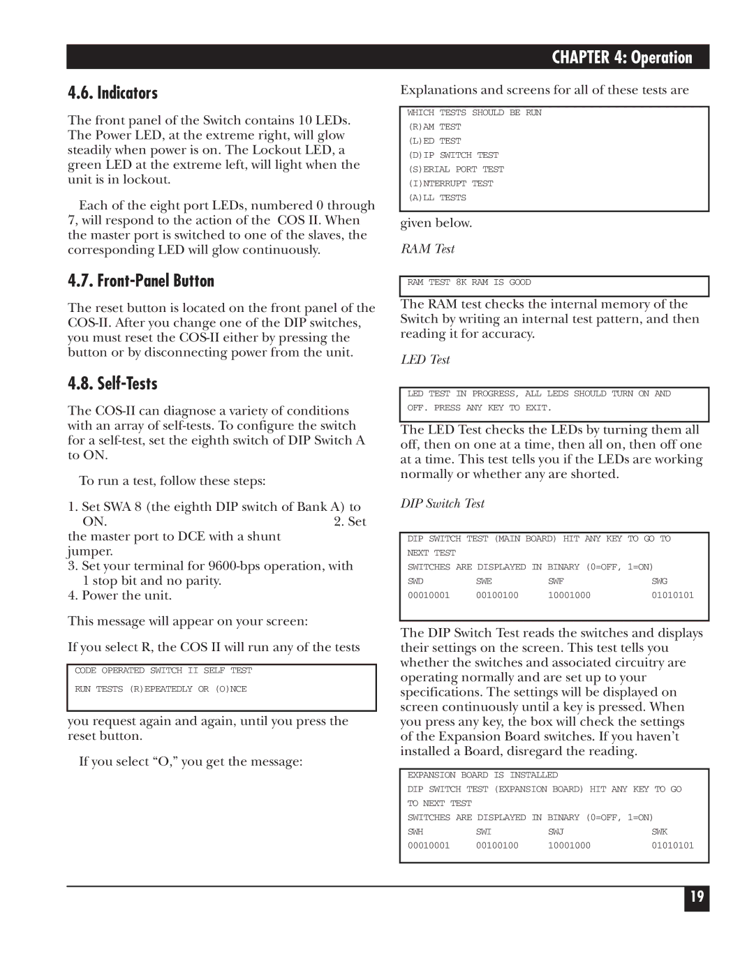
Explanations and screens for all of these tests are
WHICH TESTS SHOULD BE RUN (R)AM TEST
(L)ED TEST
(D)IP SWITCH TEST
(S)ERIAL PORT TEST
(I)NTERRUPT TEST (A)LL TESTS
given below.
RAM Test
RAM TEST 8K RAM IS GOOD
The RAM test checks the internal memory of the Switch by writing an internal test pattern, and then reading it for accuracy.
LED Test
LED TEST IN PROGRESS, ALL LEDS SHOULD TURN ON AND
OFF. PRESS ANY KEY TO EXIT.
The LED Test checks the LEDs by turning them all off, then on one at a time, then all on, then off one at a time. This test tells you if the LEDs are working normally or whether any are shorted.
DIP Switch Test
DIP SWITCH TEST (MAIN BOARD) HIT ANY KEY TO GO TO NEXT TEST
SWITCHES ARE DISPLAYED IN BINARY (0=OFF, 1=ON)
SWD | SWE | SWF | SWG |
00010001 | 00100100 | 10001000 | 01010101 |
The DIP Switch Test reads the switches and displays their settings on the screen. This test tells you whether the switches and associated circuitry are operating normally and are set up to your specifications. The settings will be displayed on screen continuously until a key is pressed. When you press any key, the box will check the settings of the Expansion Board switches. If you haven’t installed a Board, disregard the reading.
EXPANSION BOARD IS INSTALLED
DIP SWITCH TEST (EXPANSION BOARD) HIT ANY KEY TO GO TO NEXT TEST
SWITCHES ARE DISPLAYED IN BINARY (0=OFF, 1=ON)
SWH | SWI | SWJ | SWK |
00010001 | 00100100 | 10001000 | 01010101 |
19
