9421 (SS2-HE) specifications
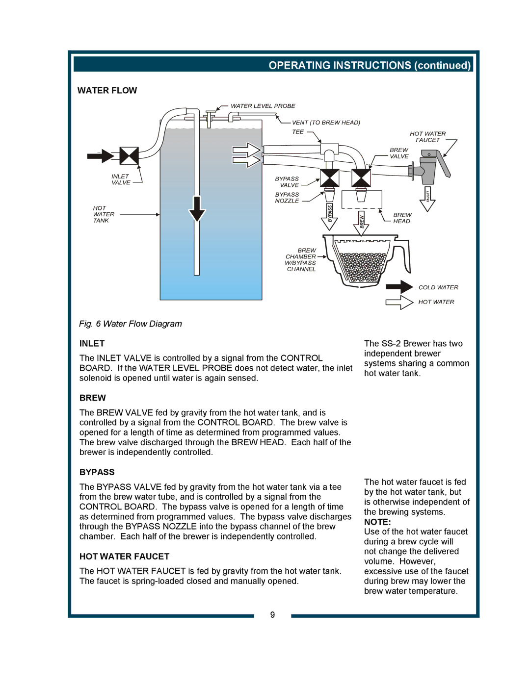
The Bloomfield 9421, also known as the SS2-HE, is a cutting-edge commercial-grade coffee brewer designed for cafes, restaurants, and other food-service establishments. This versatile machine combines advanced technology with practical features to meet the demands of high-volume coffee production while maintaining exceptional taste and quality.At the heart of the Bloomfield 9421 is its state-of-the-art brewing technology. The machine employs a precision brewing system that allows for accurate temperature control, ensuring that each batch of coffee is brewed to perfection. With a temperature range of 190°F to 205°F, the brewer can extract the ideal flavor profile from various coffee beans, catering to diverse consumer preferences.
One of the standout features of the Bloomfield 9421 is its ability to brew large quantities of coffee efficiently. With a capacity to brew up to 12 gallons of coffee per hour, it is particularly well-suited for busy establishments that require a fast turnaround. The machine is equipped with twin coffee brew baskets, enabling simultaneous brewing and allowing staff to serve customers promptly during peak hours.
In addition to its brewing capabilities, the Bloomfield 9421 incorporates user-friendly controls. An intuitive digital display provides real-time feedback on brewing parameters, allowing operators to monitor and adjust settings easily. This makes it easier for staff to maintain consistency in coffee quality, which is crucial in building customer loyalty.
Safety and convenience are also prioritized in the design of the Bloomfield 9421. The brewer features a built-in safety shut-off mechanism that activates if water levels drop too low, preventing overheating and potential damage to the machine. Furthermore, its compact design allows for easy integration into various kitchen layouts.
The materials used in the construction of the Bloomfield 9421 are of the highest quality, ensuring durability and longevity. The stainless steel exterior not only provides a sleek and professional appearance but also makes it easy to clean and maintain hygiene standards.
Overall, the Bloomfield 9421 (SS2-HE) is an exceptional choice for any establishment looking to enhance its coffee service. With its robust design, advanced brewing technology, and user-friendly interface, it stands out as a leader in the commercial coffee brewing market. Whether you're serving a fast-paced breakfast crowd or an afternoon coffee break, the Bloomfield 9421 is engineered to deliver quality coffee with every brew.

