PCM2000 specifications
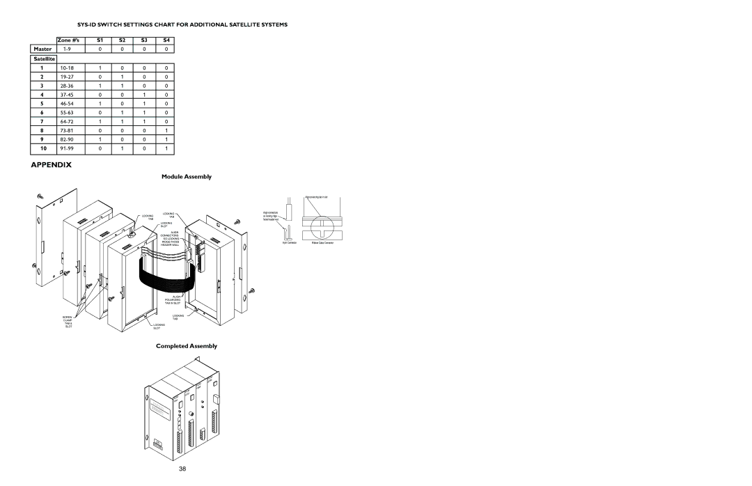
The Bogen PCM2000 is a powerful and versatile public address (PA) system designed to deliver high-quality sound in a range of environments. Whether being used in schools, offices, retail spaces, or large auditoriums, the PCM2000 is engineered to meet diverse audio requirements while ensuring user-friendly operation.One of the standout features of the PCM2000 is its modular design. This allows users to customize the system to fit their specific needs by adding or removing components. The system is built around a multi-channel amplifier, providing flexibility in configuring the sound output. The PCM2000 supports a range of audio sources, including microphones, CD players, and other auxiliary devices, making it adaptable for various applications.
The PCM2000 incorporates advanced digital signal processing (DSP) technology, which enhances overall audio quality. This technology enables features such as equalization, compression, and limiting, ensuring that the sound is clear and consistent across different environments. The system's DSP capabilities also help to minimize feedback and distortion, providing a professional-grade audio experience.
Another significant characteristic of the Bogen PCM2000 is its user-friendly interface. It features a simplified control panel that allows for intuitive operation. Users can easily adjust volume levels, select input sources, and manage other functionalities without extensive training. Additionally, the system can be integrated with existing networks, allowing for remote control and monitoring via a computer or mobile device.
The PCM2000 is highly reliable and built for long-term performance. It features a rugged construction designed to withstand the rigors of daily use, ensuring durability in commercial settings. Moreover, its efficient thermal management keeps the system cool during extended operation, reducing the risk of overheating and prolonging its lifespan.
The PCM2000 meets various safety and compliance standards, ensuring it is suitable for a wide array of installation environments. Its ability to interconnect with other systems, including fire alarms and emergency notification systems, makes it a critical component for comprehensive safety protocols.
In summary, the Bogen PCM2000 is an advanced public address system that combines modular design, sophisticated DSP technology, and user-friendly operation. Its reliability and versatility make it an excellent choice for any setting requiring clear and effective audio communication.

