
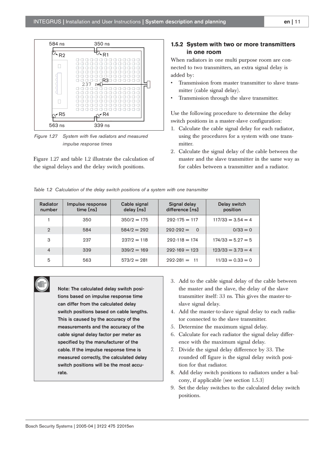
3122 475 22015en specifications
Bosch Appliances are synonymous with quality and innovation, and the model 3122 475 22015en showcases these attributes elegantly. This appliance combines advanced engineering with intuitive design, making it a valuable addition to any modern kitchen.One of the standout features of the Bosch 3122 475 22015en is its efficiency. Designed to optimize performance while using minimal energy, this appliance is ideal for environmentally-conscious consumers. It complies with strict energy standards, ensuring that it not only delivers superior results but also helps in reducing household energy bills.
The appliance is equipped with cutting-edge technology that enhances its functionality. One significant innovation is the EcoSilence Drive, which ensures powerful performance with minimal noise. This makes the Bosch 3122 475 22015en an excellent choice for open-concept living spaces or homes where silence is valued.
Another noteworthy aspect is its PrecisionWash technology. This intelligent feature uses sensors to detect soil levels, adjusting the wash cycle for optimal cleaning power. This ensures that every dish, regardless of the load, comes out sparkling clean, thus providing peace of mind for users who value cleanliness.
The design of the Bosch 3122 475 22015en is sleek and modern, with a stainless-steel finish that complements contemporary kitchen aesthetics. Its ergonomic controls are intuitive and user-friendly, making operation straightforward even for those who are not technologically savvy.
In addition to its performance and aesthetics, safety is also a priority in the design of this appliance. It includes multiple safety features such as a Child Lock for added peace of mind, ensuring a safe environment for households with young children.
Furthermore, this model incorporates flexible loading options, including adjustable racks and foldable tines, allowing users to customize the interior space to accommodate various sizes and shapes of dishes. This adaptability maximizes utility and enhances user experience.
In conclusion, the Bosch Appliances 3122 475 22015en is a perfect blend of performance, efficiency, and innovative technology. With features like EcoSilence Drive and PrecisionWash, alongside a focus on safety and flexibility, it truly embodies Bosch's commitment to creating high-quality appliances that meet the needs of modern living. Whether you are an avid chef or simply enjoy hosting, this appliance is designed to make everyday tasks easier and more efficient.