Remote control installation
B Replace the control unit cover with the 4 Philips head screws (Fig. 3, pos. 1).
B Slide control unit back into heater.
B Plug 2 yellow electrode wires from the top of the control unit back onto the ignition electrodes. Ensure all connections are secure and tight (Fig. 2, pos. 3).
i | Wire polarity does not | |
matter on the electrode | ||
| ||
| wires. |
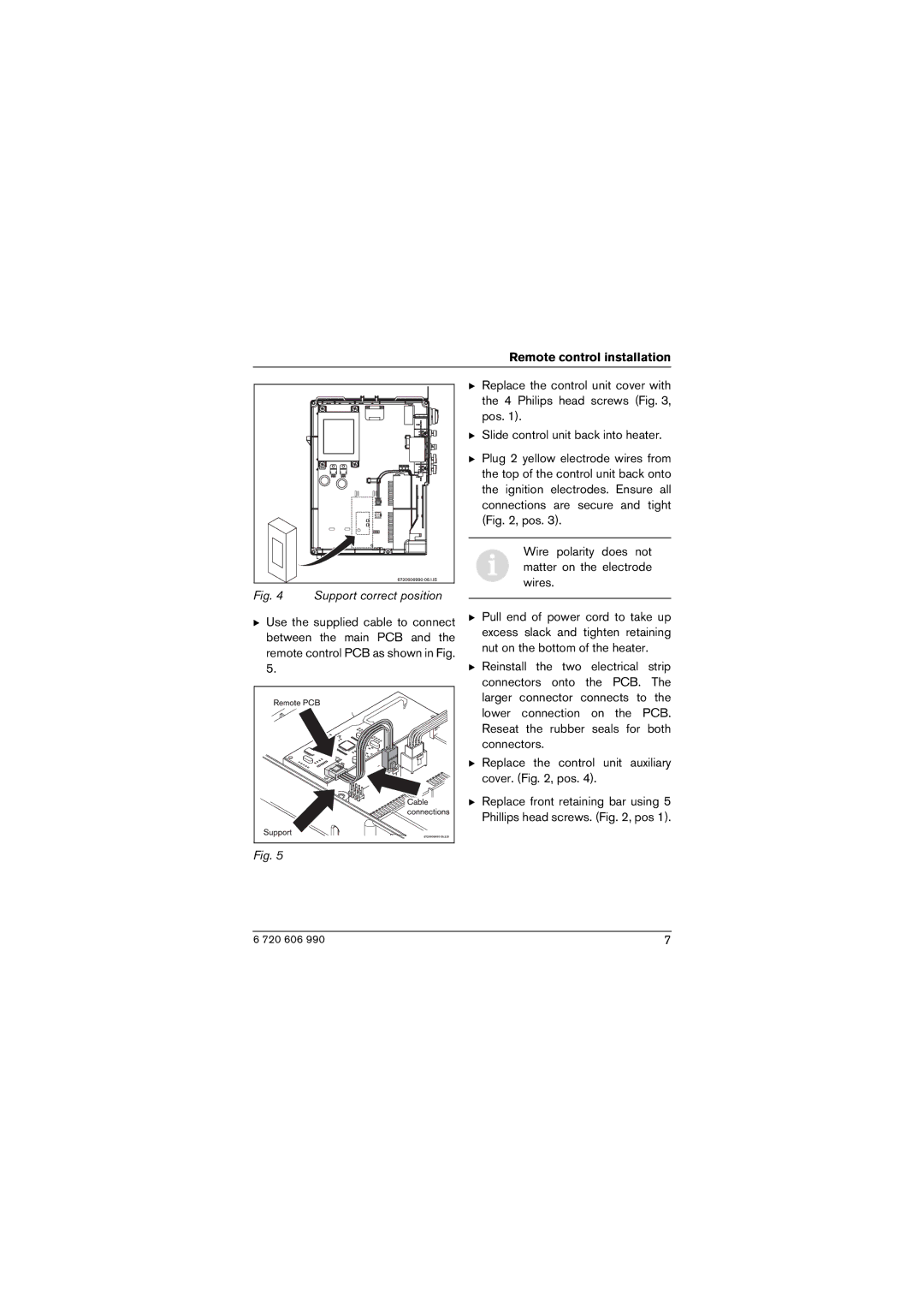
Fig. 4 Support correct position
BUse the supplied cable to connect between the main PCB and the remote control PCB as shown in Fig. 5.
B Pull end of power cord to take up excess slack and tighten retaining nut on the bottom of the heater.
B Reinstall the two electrical strip connectors onto the PCB. The larger connector connects to the lower connection on the PCB. Reseat the rubber seals for both connectors.
B Replace the control unit auxiliary cover. (Fig. 2, pos. 4).
BReplace front retaining bar using 5 Phillips head screws. (Fig. 2, pos 1).
Fig. 5
6 720 606 990 | 7 |