Remote control installation
Once auxiliary |
cover is off, pull |
off the two |
electrical strip |
connectors from |
the board. Once |
off, the wiring |
harness can be |
removed from the |
case by pulling |
their rubber seals |
outward. |
Electrical strip connectors
BAt the ignition electrodes, pull off the 2 yellow igniter wires that come from the top of the control unit (Fig. 2, pos. 3). Then pull the complete control unit forward and out of the heater, pull up the power supply cord further if more slack is needed.
BWhile holding the unit in one hand or resting it on a flat surface, remove the front cover of the control unit by removing the 4 screws.
Remote control transceiver PCB installation
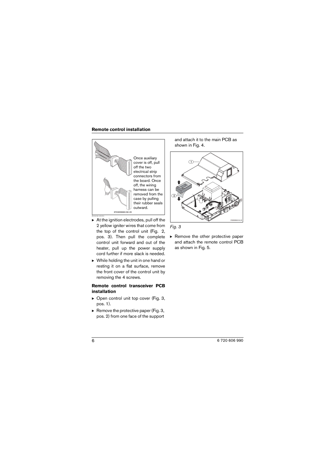
BOpen control unit top cover (Fig. 3, pos. 1).
BRemove the protective paper (Fig. 3, pos. 2) from one face of the support
and attach it to the main PCB as shown in Fig. 4.
Fig. 3
BRemove the other protective paper and attach the remote control PCB as shown in Fig. 5.
6 | 6 720 606 990 |