Full HD LCD Monitors | Monitor Panels en 19 |
|
|
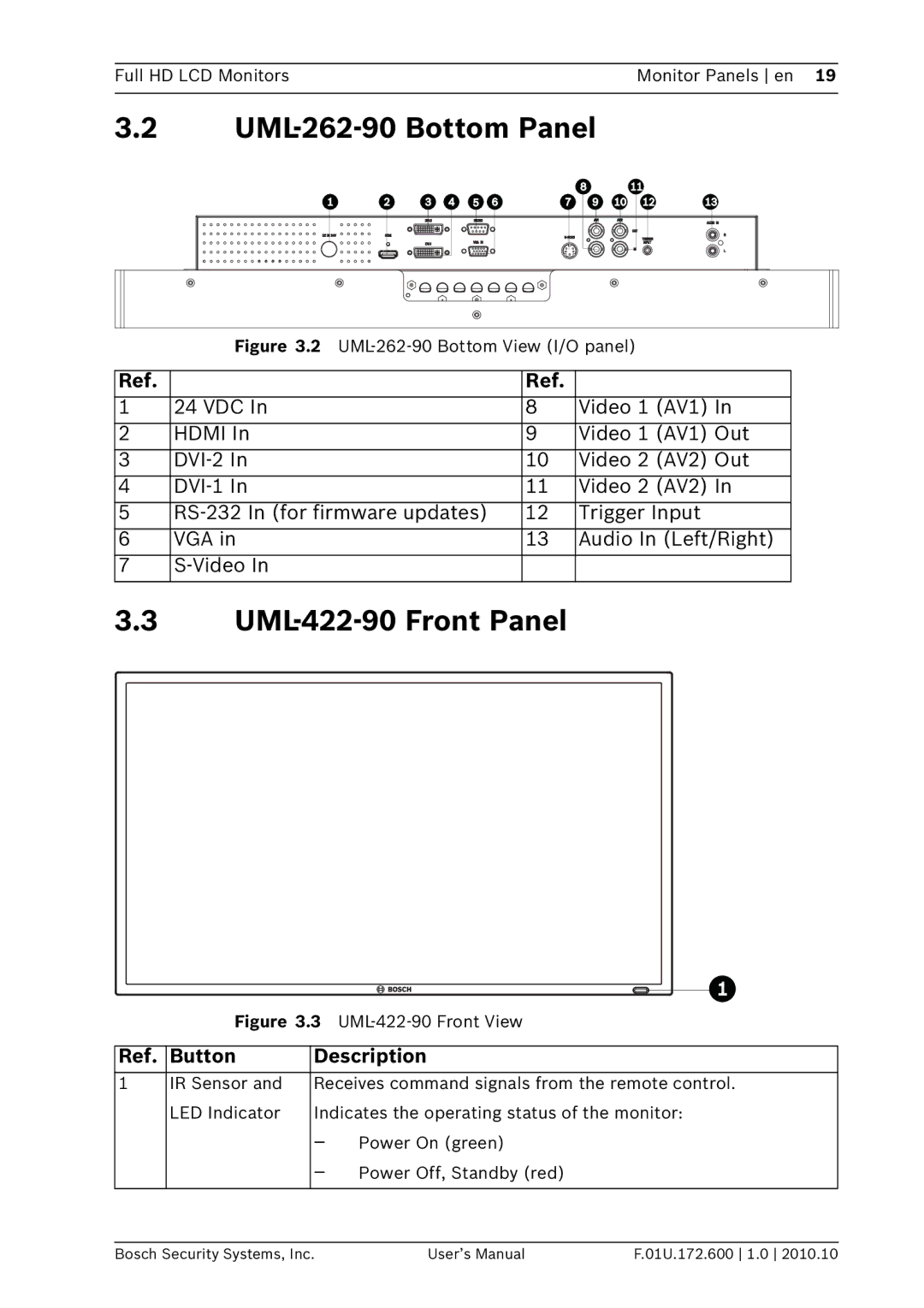
3.2UML-262-90 Bottom Panel
Figure 3.2 UML-262-90 Bottom View (I/O panel)
Ref. |
| Ref. |
|
|
1 | 24 VDC In | 8 | Video 1 (AV1) In | |
2 | HDMI In | 9 | Video 1 | (AV1) Out |
3 | 10 | Video 2 | (AV2) Out | |
4 | 11 | Video 2 | (AV2) In | |
5 | 12 | Trigger Input | ||
6 | VGA in | 13 | Audio In (Left/Right) | |
7 |
|
|
| |
3.3UML-422-90 Front Panel
| Figure 3.3 | ||
|
|
| |
Ref. | Button | Description | |
1 | IR Sensor and | Receives command signals from the remote control. | |
| LED Indicator | Indicates the operating status of the monitor: | |
|
| – | Power On (green) |
|
| – Power Off, Standby (red) | |
|
|
|
|
Bosch Security Systems, Inc. | User’s Manual | F.01U.172.600 1.0 2010.10 |