Full HD LCD Monitors | Installing the Monitor en 33 |
|
|
5.7Connecting an Alarm Trigger
The monitor contains an alarm Trigger Input and a Trigger cable. These components allow you to connect an alarm relay from a device, such as a camera or a door. Connect the two flying leads from the Trigger cable into the relay out ports of the device. Then, route the other end of the cable to the Trigger Input connector on the back panel of the monitor.
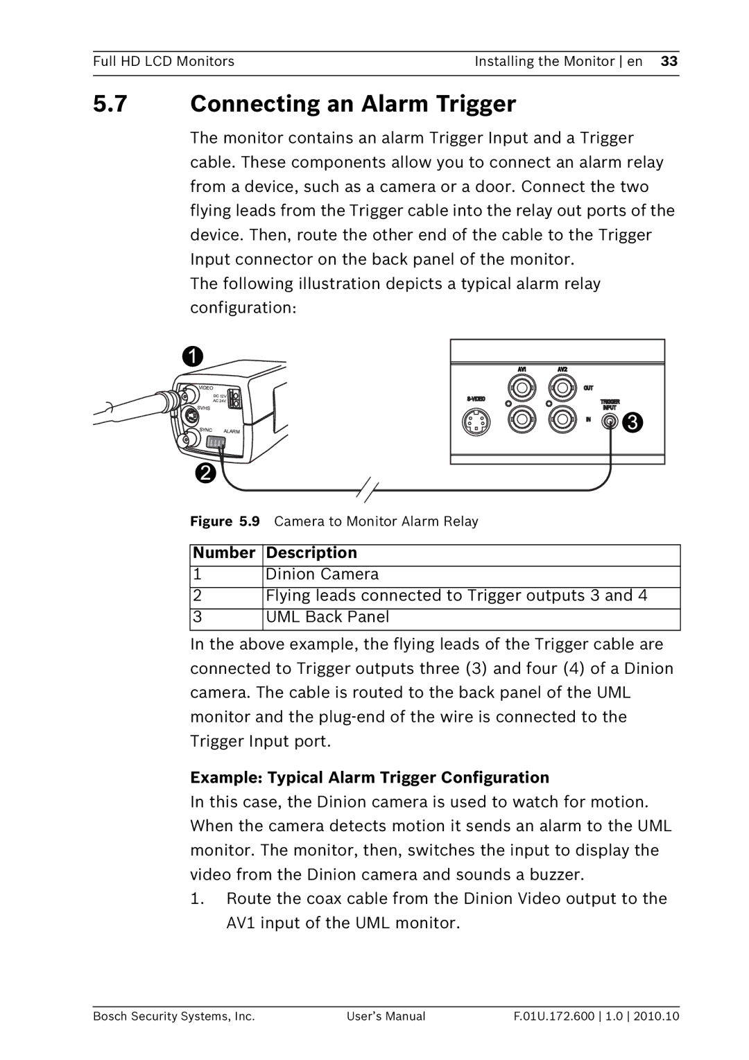
The following illustration depicts a typical alarm relay configuration:
Figure 5.9 Camera to Monitor Alarm Relay
Number Description
1Dinion Camera
2Flying leads connected to Trigger outputs 3 and 4
3 UML Back Panel
In the above example, the flying leads of the Trigger cable are connected to Trigger outputs three (3) and four (4) of a Dinion camera. The cable is routed to the back panel of the UML monitor and the
Example: Typical Alarm Trigger Configuration
In this case, the Dinion camera is used to watch for motion. When the camera detects motion it sends an alarm to the UML monitor. The monitor, then, switches the input to display the video from the Dinion camera and sounds a buzzer.
1.Route the coax cable from the Dinion Video output to the AV1 input of the UML monitor.
Bosch Security Systems, Inc. | User’s Manual | F.01U.172.600 1.0 2010.10 |