30 en Installing the Monitor | Full HD LCD Monitors |
|
|
| 400 mm |
200 mm |
|
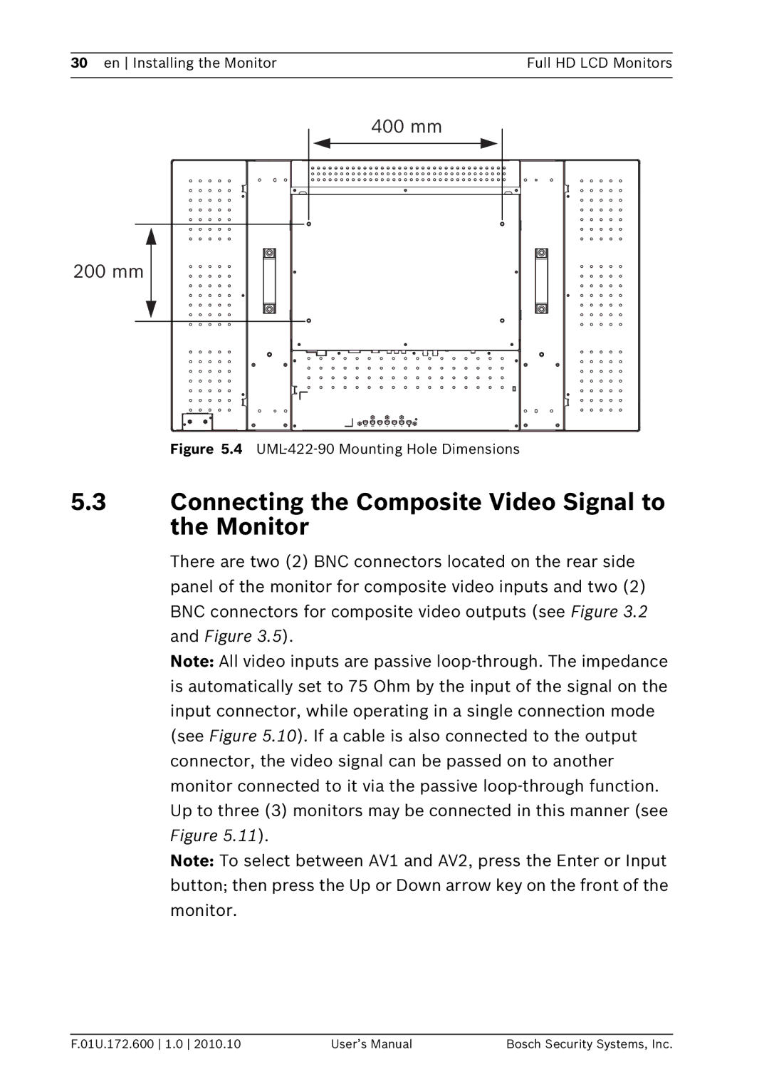
Figure 5.4 |
5.3Connecting the Composite Video Signal to the Monitor
There are two (2) BNC connectors located on the rear side panel of the monitor for composite video inputs and two (2) BNC connectors for composite video outputs (see Figure 3.2 and Figure 3.5).
Note: All video inputs are passive
Note: To select between AV1 and AV2, press the Enter or Input button; then press the Up or Down arrow key on the front of the monitor.
F.01U.172.600 1.0 2010.10 | User’s Manual | Bosch Security Systems, Inc. |