Basic Saw Operations
Auxiliary Fence - Certain types of molding need a fence face extension because of the size and position of the workpiece. Holes are provided in the fence to attach an auxiliary fence. The auxiliary fence is used with the saw in the 0° bevel position only.
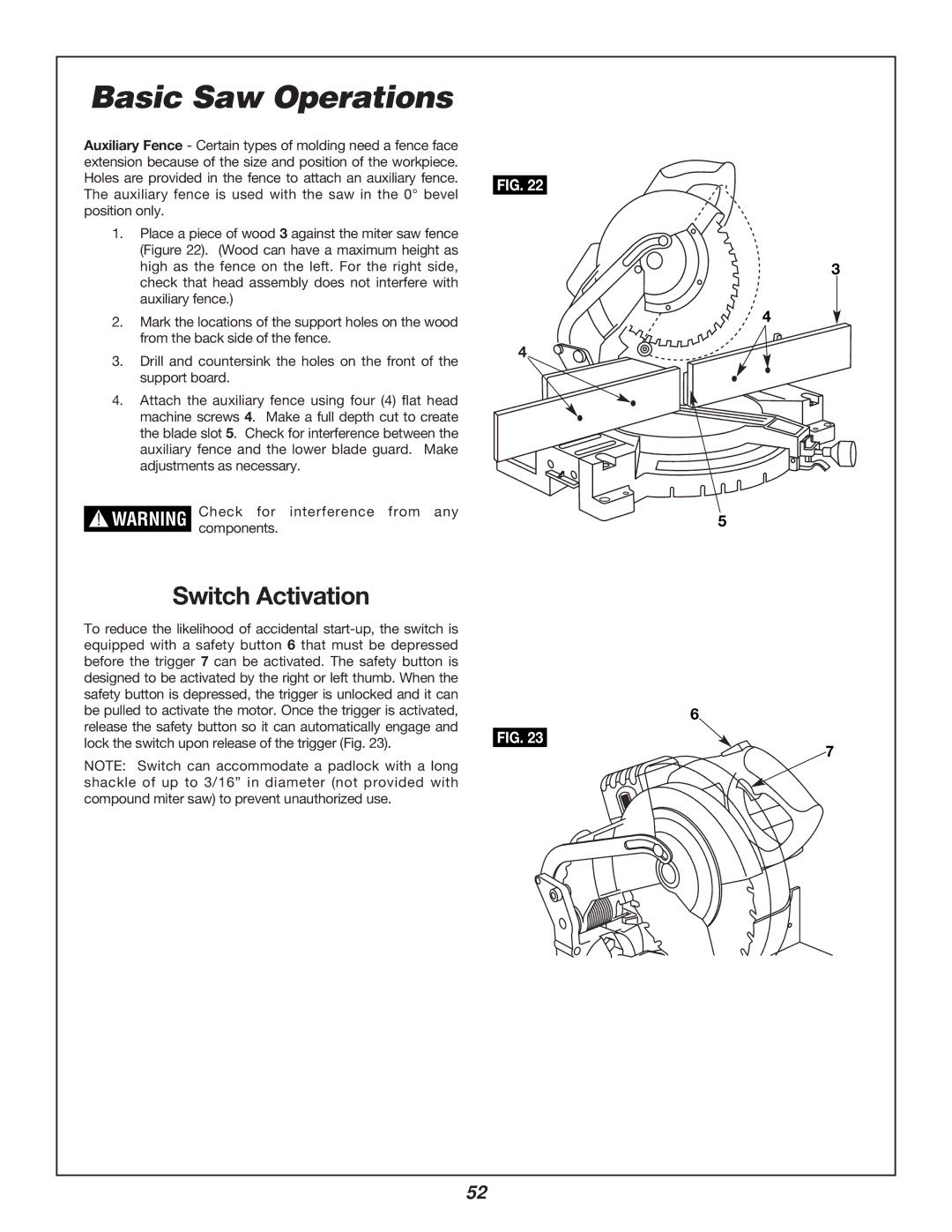
1.Place a piece of wood 3 against the miter saw fence (Figure 22). (Wood can have a maximum height as high as the fence on the left. For the right side, check that head assembly does not interfere with auxiliary fence.)
2.Mark the locations of the support holes on the wood from the back side of the fence.
3.Drill and countersink the holes on the front of the support board.
4.Attach the auxiliary fence using four (4) flat head machine screws 4. Make a full depth cut to create the blade slot 5. Check for interference between the auxiliary fence and the lower blade guard. Make adjustments as necessary.
!WARNING Check for interference from any components.
FIG. 22
3
4
4
5
Switch Activation
To reduce the likelihood of accidental |
|
equipped with a safety button 6 that must be depressed |
|
before the trigger 7 can be activated. The safety button is |
|
designed to be activated by the right or left thumb. When the |
|
safety button is depressed, the trigger is unlocked and it can |
|
be pulled to activate the motor. Once the trigger is activated, | 6 |
release the safety button so it can automatically engage and
lock the switch upon release of the trigger (Fig. 23). | FIG. 23 | |
7 | ||
NOTE: Switch can accommodate a padlock with a long | ||
| ||
shackle of up to 3/16” in diameter (not provided with |
| |
compound miter saw) to prevent unauthorized use. |
|
52