Adjustments
Miter Scale (Vernier) Indicator
Adjustment
1.Raise the head assembly to the
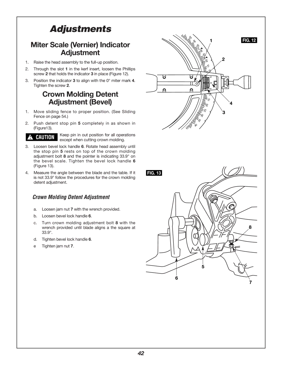
2.Through the slot 1 in the kerf insert, loosen the Phillips screw 2 that holds the indicator 3 in place (Figure 12).
3.Position the indicator 3 to align with the 0° miter mark 4. Tighten the screw 2.
Crown Molding Detent
Adjustment (Bevel)
1.Move sliding fence to proper position. (See Sliding Fence on page 54.)
2.Push detent stop pin 5 completely in as shown in (Figure13).
! CAUTION | Keep pin in out position for all operations | |
except when cutting crown molding. | ||
|
3.Loosen bevel lock handle 6. Rotate head assembly until the stop pin 5 rests on top of the crown molding adjustment bolt 8 and the pointer is indicating 33.9° on the bevel scale. Tighten the bevel lock handle 6 (Figure 13).
4. Measure the angle between the blade and the table. If it FIG. 13 is not 33.9° follow the procedures for the crown molding
detent adjustment.
Crown Molding Detent Adjustment
a.Loosen jam nut 7 with the wrench provided.
b.Loosen bevel lock handle 6.
c.Turn crown molding adjustment bolt 8 with the wrench provided until blade aligns a the square at 33.9°.
d.Tighten bevel lock handle 6.
e Tighten jam nut 7.
45
40 | 1 |
35 | |
| 316 |
| 30 |
| 25 |
| 225 |
| 20 |
| 15 |
| 10 |
| 5 |
| 0 |
| 5 |
| 10 |
| 15 |
| 20 |
| 25 |
| 30 |
| 35 |
40 |
|
FIG. 12
2
4
3
8
5
6
7
42