Adjustments | FIG. 6 |
|
!WARNING Disconnect battery pack from tool before performing any assembly,
adjustments, changing accessories, or storing the tool. Such preventive safety measures reduce the risk of starting the tool accidentally.
NOTE: Your compound miter saw was completely adjusted at the factory. However, during shipment, slight misalignment may have occurred. Check the following settings and adjust if necessary prior to using this compound miter saw.
Blade Square to Table (90°)
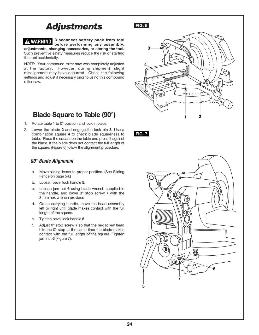
1.Rotate table 1 to 0° position and lock in place.
2.Lower the blade 2 and engage the lock pin 3. Use a combination square 4 to check blade squareness to table. Place the square on the table and press it against the blade. If the blade does not contact the full length of the square, (Figure 6) follow the alignment procedure.
3
4
1 2
FIG. 7
90° Blade Alignment
a.Move sliding fence to proper position. (See Sliding
Fence on page 54.)
b.Loosen bevel lock handle 5.
c.Loosen jam nut 6 using blade wrench supplied in the handle, and lower 0° stop screw 7 with the 3 mm hex wrench provided.
d.Grasp carrying handle, move the head assembly left or right until blade makes contact with the full length of the square.
e.Tighten bevel lock handle 5.
f.Adjust 0° stop screw 7 so that the hex screw head hits the 0° stop at the same time the blade makes contact with the full length of the square. Tighten jam nut 6 (Figure 7).
6
7
5
34
