Manuals
/
Bradford-White Corp
/
Household Appliance
/
Water Heater
Bradford-White Corp
BWCV Table Of Contents, General Information, Venting and Combustion Air
Models:
BWCV
1
2
44
44
Download
44 pages
23.82 Kb
1
2
3
4
5
6
7
8
Troubleshooting
SECTION Wiring Diagrams
Error Displayed
Field Wiring
Warranty
Dimension
Maintenance
Outdoor Reset Operation
Main Power
Flow Switch
Page 2
Image 2
Page 1
Page 3
Page 2
Image 2
Page 1
Page 3
Contents
Installation and Operation Instructions
Internet Version for Reference Only
Installation and Operation Instructions for
Copper Brute
SECTION 8. Trouble Shooting
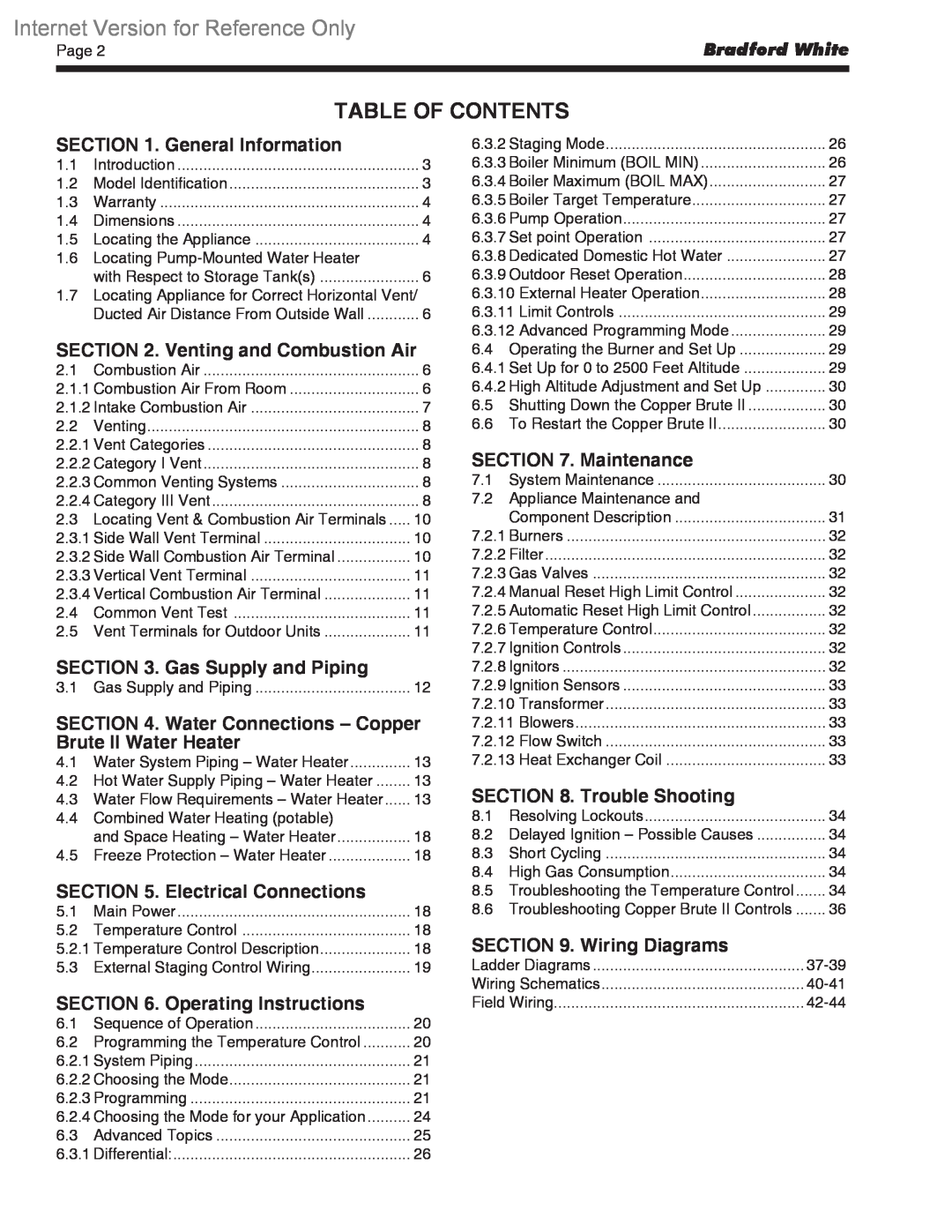
TABLE OF CONTENTS
SECTION 7. Maintenance
SECTION 9. Wiring Diagrams
1.2 Model Identification
SECTION General Information
1.1 Introduction
1.5 Locating the Appliance
1.4 Dimensions
1.3 Warranty
Figure 1. Dimensional Data
From Outside Wall
SECTION Venting and Combustion Air
1.6 Locating Pump-Mounted Water Heater with Respect to Storage Tanks
2.1 Combustion Air
2.1.2 Intake Combustion Air
2.2.2 Category I Vent
2.2 Venting
2.2.1 Vent Categories
2.2.3 Common Venting Systems
Figure 3. Combustion Air and Vent Through Side Wall
2.3.1 Side Wall Vent Terminal
2.3 Locating Vent & Combustion Air Terminals
Important Note Massachusetts Code Requirement
2.3.2 Side Wall Combustion Air Terminal
2.3.3 Vertical Vent Terminal
2.4 Common Vent Test
2.5 Vent Terminals for Outdoor Units
2.3.4 Vertical Combustion Air Terminal
SECTION Gas Supply and Piping
3.1 Gas Supply and Piping
4.2 Hot Water Supply Piping - Water Heater
SECTION Water Connections Copper Brute II Water Heater
4.1 Water System Piping Water Heater
4.3 Water Flow Requirements - Water Heater
Table 8. Water Flow Requirements
Figure 4. Water Heater Piping - One Heater, One Tank
Figure 5. Water Heater Piping - Multiple Heaters, One Tank
Figure 6. Water Heater Piping - One Heater, Multiple Tanks
Figure 7. Water Heater Piping - Multiple Heaters, Multiple Tanks
4.4 Combined Water Heating potable and Space Heating - Water Heater
5.1 Main Power
SECTION Electrical Connections
4.5 Freeze Protection - Water Heater
5.3 External Staging Control Wiring
AVERTISSEMENT
6.2 Programming the Temperature Control
SECTION Operating Instructions
6.1 Sequence of Operation
6.2.2 Choosing the Mode
6.2.1 System Piping “Primary Secondary Piping”
“Parallel Piping”
6.2.3 Programming
6.3.3 for more information BOIL MAX Boiler Maximum Temperature
Boiler Start BOIL START The BOIL
6.2.4 Choosing the Mode for your Application
Mechanical aquastat in a domestic hot water storage tank
6.3 Advanced Topics
Mode 5 Primary secondary piping with outdoor reset
6.3.3 Boiler Minimum BOIL MIN
6.3.1 Differential
6.3.2 Staging Mode
6.3.6 Pump Operation
6.3.4 Boiler Maximum BOIL MAX
6.3.5 Boiler Target Temperature
6.3.7 Set point Operation
6.3.10 External Heater Operation
6.3.9 Outdoor Reset Operation
Outdoor Design OUTDR DSGN - The
6.3.11 Limit Controls
6.4 Operating the Burner and Set Up
6.4.1 Set Up for 0 to 2500 Feet Altitude
6.3.12 Advanced Programming Mode
6.5 Shutting Down the Copper Brute
SECTION Maintenance
7.1 System Maintenance
6.6 To Restart the Copper Brute
7.2 Appliance Maintenance and Component Description
7.2.1 Burners
7.2.4 Manual Reset High Limit Control
7.2.5 Automatic Reset High Limit Control
7.2.2 Filter
7.2.10 Transformer
7.2.12 Flow Switch
7.2.9 Ignition Sensors
7.2.11 Blowers
8.2 Delayed Ignition - Possible Causes
SECTION Trouble Shooting
8.1 Resolving Lockouts
8.3 Short Cycling
ERROR DISPLAYED
DESCRIPTION OF ERROR
8.6 Troubleshooting Copper Brute II Controls
SECTION Wiring Diagrams
Figure 18. Copper Brute II 500 - 750 Ladder Diagram
Figure 19. Copper Brute II 1000 Ladder Diagram
Figure 20. Copper Brute II 1250 - 2000 Ladder Diagram
Figure 21. Copper Brute II 500 - 1000 Wiring Schematic
Figure 22. Copper Brute II 1250 - 2000 Wiring Schematic
terminal designations are as indicated
Note Positions of field wiring terminals may vary, but
Figure 23. Field Wiring
Figure 24. Field
Reference Only
Wiring for Modes 1
MODE
Internet
Version for Reference Only
25. Field Wiring for Mode
Copper Brute II 1250, 1500, 1750 & 2000 4-Stage Heater
Top
Page
Image
Contents