SERVICE PROCEDURE AG-III
Gas Control Testing and Replacement
For Models using White Rodgers or
Robertshaw Gas Control
Gas Control Testing and Replacement
The gas control is a non repairable device. If trouble shooting has determined a problem with the gas control, it must be replaced.
If the burner and/or pilot do not function, service checks for gas pressure, thermocouple output, magnet assembly and ECO are to be performed. If these check OK, the gas control may be faulty.
LINE PRESSURE
The gas control is designed for a maximum line pressure of 14.0" w.c. and a minimum line pressure of 1.0"w.c. over the water heater rated manifold pressure. Line pressure must be checked with burner on and burner off to assure proper readings.
MANIFOLD PRESSURE TESTING (this procedure assumes a maximum line pressure of 14.0" w.c.)
Step 1. Set gas control to “OFF” position.
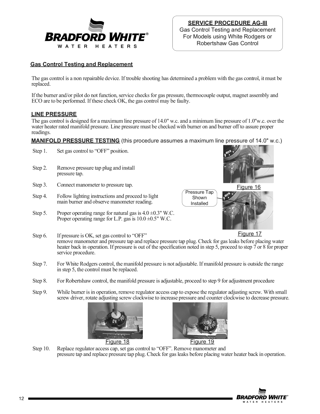
Step 2. Remove pressure tap plug and install pressure tap.
Step 3. Connect manometer to pressure tap.
Step 4. Follow lighting instructions and proceed to light main burner and observe manometer reading.
Step 5. Proper operating range for natural gas is 4.0 ±0.3" W.C. Proper operating range for L.P. gas is 10.0 ±0.5" W.C.
Figure 16
Pressure Tap
Shown
Installed
Step 6. If pressure is OK, set gas control to “OFF”Figure 17 remove manometer and pressure tap and replace pressure tap plug. Check for gas leaks before placing water heater back in operation. If pressure is out of the specification noted in step 5, proceed to step 7 or 8 for proper service procedure.
Step 7. For White Rodgers control, the manifold pressure is not adjustable. If manifold pressure is outside the range in step 5, the control must be replaced.
Step 8. For Robertshaw control, the manifold pressure is adjustable, proceed to step 9 for adjustment procedure
Step 9. While burner is in operation, remove regulator access cap to expose the regulator adjusting screw. With small screw driver, rotate adjusting screw clockwise to increase pressure and counter clockwise to decrease pressure.
Figure 18 |
| Figure 19 |
Step 10. Replace regulator access cap, set gas control to “OFF”. Remove manometer and
pressure tap and replace pressure tap plug. Check for gas leaks before placing water heater back in operation.
Page 12
12