Step7
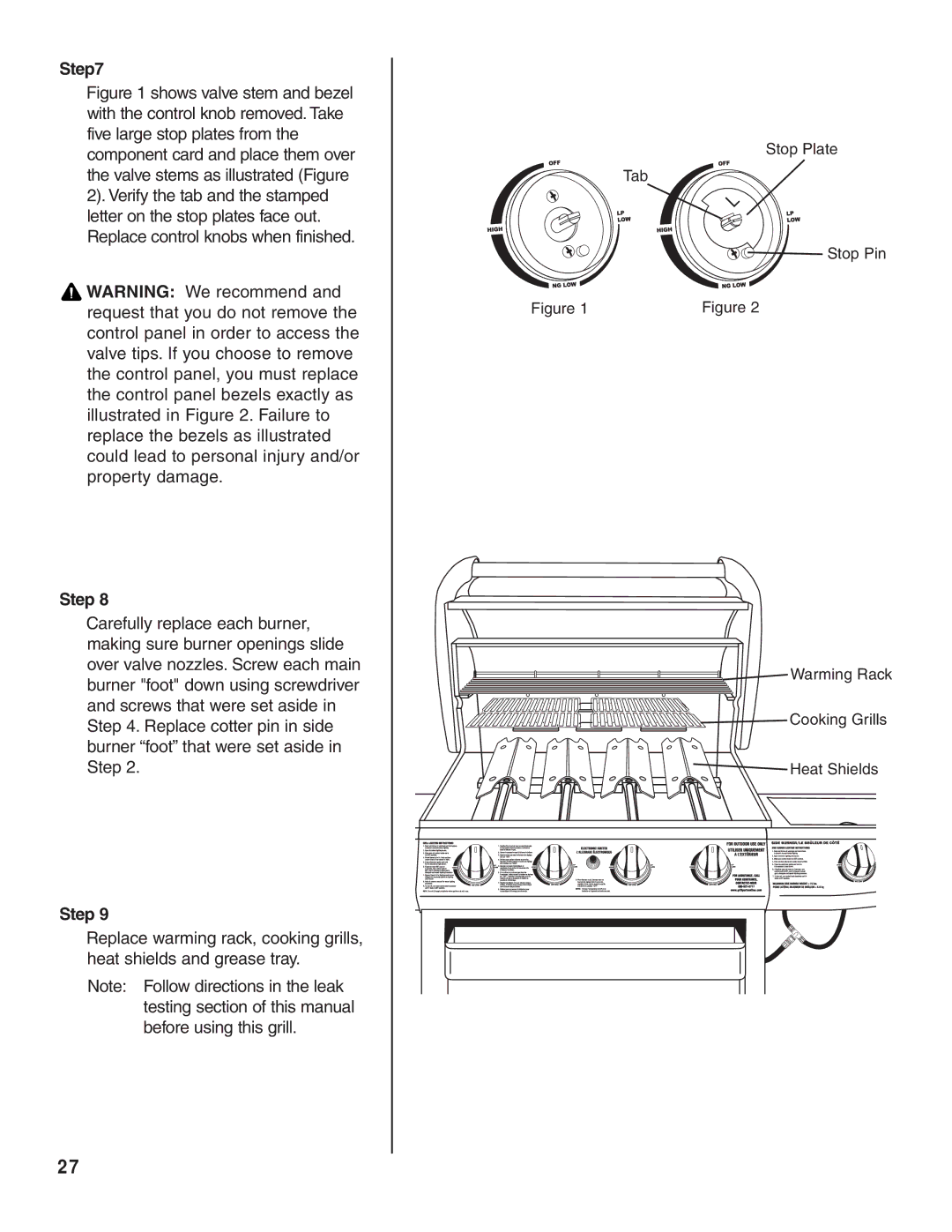
Figure 1 shows valve stem and bezel with the control knob removed. Take five large stop plates from the component card and place them over the valve stems as illustrated (Figure 2). Verify the tab and the stamped letter on the stop plates face out. Replace control knobs when finished.
![]() WARNING: We recommend and request that you do not remove the control panel in order to access the valve tips. If you choose to remove the control panel, you must replace the control panel bezels exactly as illustrated in Figure 2. Failure to replace the bezels as illustrated could lead to personal injury and/or property damage.
WARNING: We recommend and request that you do not remove the control panel in order to access the valve tips. If you choose to remove the control panel, you must replace the control panel bezels exactly as illustrated in Figure 2. Failure to replace the bezels as illustrated could lead to personal injury and/or property damage.
Step 8
Carefully replace each burner, making sure burner openings slide over valve nozzles. Screw each main burner "foot" down using screwdriver and screws that were set aside in Step 4. Replace cotter pin in side burner “foot” that were set aside in Step 2.
Step 9
Replace warming rack, cooking grills, heat shields and grease tray.
Note: Follow directions in the leak testing section of this manual before using this grill.
Stop Plate
Tab
Stop Pin
Figure 1 | Figure 2 |
![]() Warming Rack
Warming Rack
![]() Cooking Grills
Cooking Grills
![]()
![]() Heat Shields
Heat Shields
27