d.Use inducer housing drain tube (violet label and factory- supplied in loose parts bag) to connect LOWER inducer housing drain connection to the condensate trap.

e.Connect inducer housing drain connection to condensate trap.

(1.)

Condensate Trap Located on Left Side of Casing


(a.)

Determine appropriate length and cut.


(b.)

Connect tube to condensate trap.


(c.)

Clamp tube to prevent any condensate leakage.

(2.)

Condensate Trap Located on Right Side of Casing

(a.)

Route inducer housing drain tube (violet label)


directly from inducer housing to condensate


trap as shown in Fig. 8.


(b.)

Determine appropriate length and cut.


(c.)

Connect tube to condensate trap.


(d.)

Clamp tube to prevent any condensate leakage.

3.Relief Port Tube

Refer to Pressure Switch Tubing section for connection procedure.

C.Condensate Trap Field Drain Attachment

Refer to Condensate Drain section for recommendations and procedures.

D.Pressure Switch Tubing

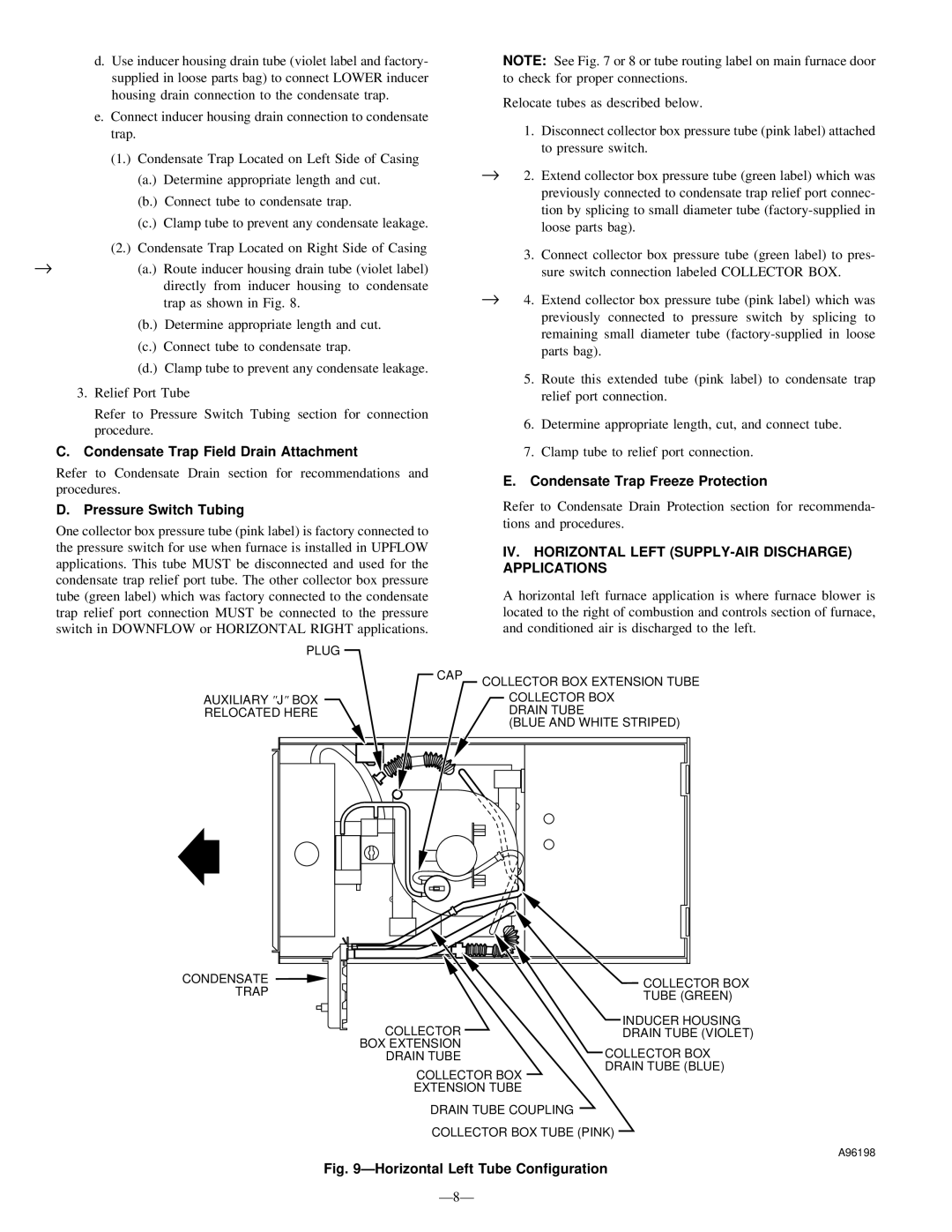
One collector box pressure tube (pink label) is factory connected to the pressure switch for use when furnace is installed in UPFLOW applications. This tube MUST be disconnected and used for the condensate trap relief port tube. The other collector box pressure tube (green label) which was factory connected to the condensate trap relief port connection MUST be connected to the pressure switch in DOWNFLOW or HORIZONTAL RIGHT applications.

NOTE: See Fig. 7 or 8 or tube routing label on main furnace door to check for proper connections.

Relocate tubes as described below.

1.Disconnect collector box pressure tube (pink label) attached to pressure switch.

2. Extend collector box pressure tube (green label) which was previously connected to condensate trap relief port connec- tion by splicing to small diameter tube (factory-supplied in loose parts bag).

3.Connect collector box pressure tube (green label) to pres- sure switch connection labeled COLLECTOR BOX.

4. Extend collector box pressure tube (pink label) which was previously connected to pressure switch by splicing to remaining small diameter tube (factory-supplied in loose parts bag).

5.Route this extended tube (pink label) to condensate trap relief port connection.

6.Determine appropriate length, cut, and connect tube.

7.Clamp tube to relief port connection.

E. Condensate Trap Freeze Protection

Refer to Condensate Drain Protection section for recommenda- tions and procedures.

IV. HORIZONTAL LEFT (SUPPLY-AIR DISCHARGE) APPLICATIONS

A horizontal left furnace application is where furnace blower is located to the right of combustion and controls section of furnace, and conditioned air is discharged to the left.

PLUG


CAP

COLLECTOR BOX EXTENSION TUBE


AUXILIARY "J" BOX


COLLECTOR BOX

RELOCATED HERE


DRAIN TUBE


(BLUE AND WHITE STRIPED)

CONDENSATE

COLLECTOR BOX

TRAP

TUBE (GREEN)


COLLECTOR

INDUCER HOUSING

DRAIN TUBE (VIOLET)

BOX EXTENSION

COLLECTOR BOX

DRAIN TUBE


DRAIN TUBE (BLUE)

COLLECTOR BOX

EXTENSION TUBE

DRAIN TUBE COUPLING

COLLECTOR BOX TUBE (PINK)

A96198

Fig. 9ÐHorizontal Left Tube Configuration

Ð8Ð

Page 8
Image 8
Bryant 340MAV instruction manual IV. Horizontal Left SUPPLY-AIR Discharge Applications, Ð8Ð

340MAV specifications

The Bryant 340MAV is a standout model in the Bryant lineup, designed to provide exceptional comfort, efficiency, and performance for residential heating and cooling needs. This unit offers a perfect blend of innovative technology and user-friendly features, making it an ideal choice for homeowners seeking reliability and quality.

One of the defining characteristics of the Bryant 340MAV is its impressive efficiency rating. With a SEER (Seasonal Energy Efficiency Ratio) of up to 18, this model ensures that homeowners can enjoy effective cooling during the summer months while minimizing energy consumption. Similarly, the heating efficiency is notable, with a high AFUE (Annual Fuel Utilization Efficiency) rating. This makes the 340MAV an environmentally friendly option that also promotes cost savings on energy bills.

The 340MAV incorporates advanced technologies that enhance its performance. One such technology is the variable-speed compressor, which allows the system to adjust its output based on the demands of the home. This means that the unit operates more quietly and reduces energy usage by matching the cooling or heating output required. Additionally, the two-stage heating capability provides more consistent temperatures and improved comfort throughout the space.

Operating noise is a crucial factor in residential HVAC systems, and the Bryant 340MAV is designed with this in mind. Engineered for quiet operation, the unit features a sound-dampening design, including an insulated cabinet and a specially designed compressor that minimizes noise levels. Homeowners can enjoy a comfortable indoor climate without the disruptive racket often associated with traditional systems.

Furthermore, the Bryant 340MAV is equipped with a durable all-aluminum coil, which improves heat transfer efficiency while also being resistant to corrosion. This characteristic contributes to the longevity of the unit, ensuring that it can withstand various environmental factors without compromising performance.

Another key feature is the advanced control options that the Bryant 340MAV offers. Integration with smart thermostats allows homeowners to monitor and adjust their HVAC system remotely, ensuring optimal comfort at all times. Additionally, the system is compatible with Bryant's Perfect Air™ filtration system, enhancing indoor air quality by reducing pollutants and allergens.

In summary, the Bryant 340MAV is a high-efficiency heating and cooling solution that brings together cutting-edge technology, quiet operation, and user-friendly features. With its focus on comfort and energy savings, it stands out as a prime choice for homeowners looking to invest in a reliable HVAC system.