The ®eld-supplied disconnect switch box may be mounted on the unit's end panel or on the corner post. Mount disconnect box on the left side of the rating plate when mounting on the unit's end panel. Do not mount the disconnect box over the unit rating plate. When mounting disconnect box on corner post, secure disconnect box to corner post and condenser coil top cover. See Fig. 12.

A disconnect box mounting space is available when an op- tional or accessory condenser coil grille is used. Mount the disconnect on the sheet metal provided with the condenser coil grille. The sheet metal is located adjacent to the corner post on the left side of the power wiring access panel.

Install ®eld wiring as follows:

1.Connect ground lead to chassis ground connection when using separate ground wire.

2.Install conduit between disconnect and power wiring ac- cess panel. Insert conduit through power supply knock- out opening. See Fig. 12.

3.Install power lines to power wiring leads.

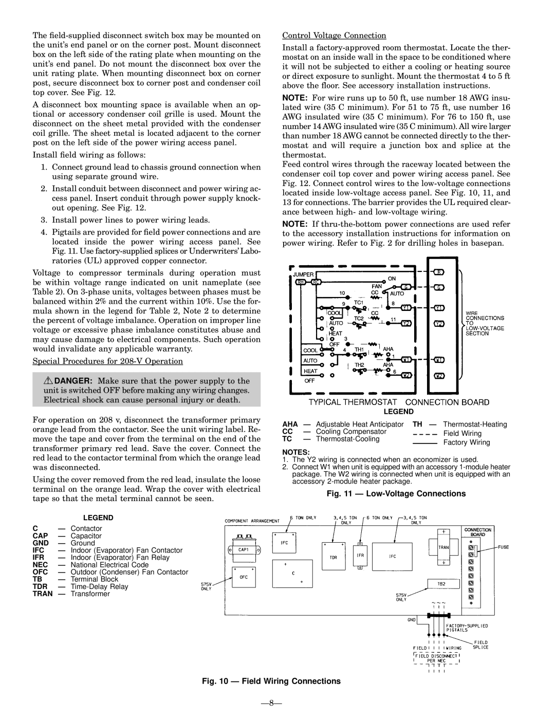
4.Pigtails are provided for ®eld power connections and are located inside the power wiring access panel. See Fig. 11. Use factory-supplied splices or Underwriters' Labo- ratories (UL) approved copper connector.

Voltage to compressor terminals during operation must be within voltage range indicated on unit nameplate (see Table 2). On 3-phase units, voltages between phases must be balanced within 2% and the current within 10%. Use the for- mula shown in the legend for Table 2, Note 2 to determine the percent of voltage imbalance. Operation on improper line voltage or excessive phase imbalance constitutes abuse and may cause damage to electrical components. Such operation would invalidate any applicable warranty.

Special Procedures for 208-V Operation

DANGER: Make sure that the power supply to the unit is switched OFF before making any wiring changes. Electrical shock can cause personal injury or death.

For operation on 208 v, disconnect the transformer primary orange lead from the contactor. See the unit wiring label. Re- move the tape and cover from the terminal on the end of the transformer primary red lead. Save the cover. Connect the red lead to the contactor terminal from which the orange lead was disconnected.

Using the cover removed from the red lead, insulate the loose terminal on the orange lead. Wrap the cover with electrical tape so that the metal terminal cannot be seen.

LEGEND

CÐ Contactor CAP Ð Capacitor GND Ð Ground

IFC

Ð Indoor (Evaporator) Fan Contactor

IFR

Ð Indoor (Evaporator) Fan Relay

NEC

Ð National Electrical Code

OFC

Ð Outdoor (Condenser) Fan Contactor

TB

Ð Terminal Block

TDR

Ð Time-Delay Relay

TRAN Ð Transformer

Control Voltage Connection

Install a factory-approved room thermostat. Locate the ther- mostat on an inside wall in the space to be conditioned where it will not be subjected to either a cooling or heating source or direct exposure to sunlight. Mount the thermostat 4 to 5 ft above the ¯oor. See accessory installation instructions.

NOTE: For wire runs up to 50 ft, use number 18 AWG insu- lated wire (35 C minimum). For 51 to 75 ft, use number 16 AWG insulated wire (35 C minimum). For 76 to 150 ft, use number 14 AWG insulated wire (35 C minimum). All wire larger than number 18 AWG cannot be connected directly to the ther- mostat and will require a junction box and splice at the thermostat.

Feed control wires through the raceway located between the condenser coil top cover and power wiring access panel. See Fig. 12. Connect control wires to the low-voltage connections located inside low-voltage access panel. See Fig. 10, 11, and 13 for connections. The barrier provides the UL required clear- ance between high- and low-voltage wiring.

NOTE: If thru-the-bottom power connections are used refer to the accessory installation instructions for information on power wiring. Refer to Fig. 2 for drilling holes in basepan.


LEGEND


AHA Ð Adjustable Heat Anticipator TH Ð

Thermostat-Heating

CC

Ð Cooling Compensator

Field Wiring

TC

Ð Thermostat-Cooling

Factory Wiring


NOTES:

1.The Y2 wiring is connected when an economizer is used.

2.Connect W1 when unit is equipped with an accessory 1-module heater package. The W2 wiring is connected when unit is equipped with an accessory 2-module heater package.

Fig. 11 Ð Low-Voltage Connections

Fig. 10 Ð Field Wiring Connections

Ð8Ð

Page 8
Image 8
Bryant 558D installation instructions Low-Voltage Connections

558D specifications

The Bryant 558D represents a leading-edge model in the realm of advanced heating, ventilation, and air conditioning (HVAC) systems. Designed for both residential and light commercial applications, this unit brings together efficiency, performance, and reliability, making it a go-to choice for homeowners and contractors alike.

One of the standout features of the Bryant 558D is its high-efficiency rating. With SEER (Seasonal Energy Efficiency Ratio) ratings that can reach up to 18, it allows homeowners to enjoy significant savings on electricity bills while maintaining a comfortable indoor environment. The system is powered by advanced compressors that ensure optimal performance across various climate conditions, providing consistent cooling and heating as needed.

In terms of technology, the Bryant 558D incorporates a two-stage cooling system, which allows for better temperature control and humidity management. This technology enhances comfort by preventing the system from frequently starting and stopping, thus reducing wear and tear while extending the unit's lifespan. The variable-speed blower motor further contributes to this efficiency by adjusting its speed to meet the precise needs of the space, ensuring optimal air distribution and comfort.

Durability is another hallmark of the Bryant 558D. The unit is built with high-quality materials, including a galvanized steel cabinet coated with a sleek, weather-resistant finish that protects against rust and environmental wear. Its compact design makes installation seamless, allowing it to fit into various spaces without significant modifications.

The Bryant 558D also features smart technology compatibility, allowing users to integrate it with modern home automation systems. This connectivity provides homeowners with remote control capabilities, enabling them to regulate their home’s temperature via smartphone applications. This not only adds to convenience but also supports energy management strategies, as users can adjust settings based on occupancy and lifestyle patterns.

Finally, noise levels have been an important consideration in the design of the Bryant 558D. With innovative sound-dampening features, the unit operates quietly, making it an ideal choice for residential areas where noise sensitivity is paramount.

Overall, the Bryant 558D stands out as a sophisticated solution for heating and cooling needs, combining energy efficiency, advanced technology, durability, and user-friendly features. It is an excellent investment for those looking to enhance their home comfort while also being mindful of energy consumption.