0.90


0.80


wg)(in.

0.70


0.60


DROP


0.50


PRESSURE


0.40


0.30


0.20


0.10


0.00


100

200

300

400

500

600

700

800


CFM


Fig. 27 Ð Durablade Economizer Barometric Relief

Damper Characteristics

d.After installation is complete, calculate the mini- mum air¯ow across the economizer. To calculate the minimum air¯ow, the following data is needed:

total cfm (cfm3), temperature of the total cfm (T3), temperature of the return air (T2), and tempera- ture of the entering outside air (T1). Cfm1 is the outside air cfm, which will be the minimum air¯ow.

Insert the data into the following equations:

T1 (cfm1) + T2 (cfm2)

cfm3

= T3

cfm2 = (cfm3 − cfm1) Therefore:

T1 (cfm1) + T2 (cfm3 − cfm1)

cfm3

= T3


B

REV


.


MINIMUM


B


C

1


9

OPEN


D

S

TR

8


S


8


O

1


8


POSITION

1


A


T

3


P


T1

4

2

5


P1


30

60

70


AT

CONTACT

OR

CONTACTS

3


UH%


RUSH


ID IM

90


UNPOWERED


50


C

24VAC


YT


DAMPER


ATE


ENTHALPY


60


5A


2


10


D

CW


RATINGS:

ST SHOWN


TR


OUTDOOR

55


OPEN


B

SETPOINTS


24VAC


3 .


HIGH


A


1


IN


75


CLOSED DAMPER


mA

RUN,


TR1

CONTROL

F


VDC


1

TEMP

65 70


MIN


ENTHALPY


°


CCW

11

IN


.

3


.


AT

5A


.


80


85


REV.

97-3672


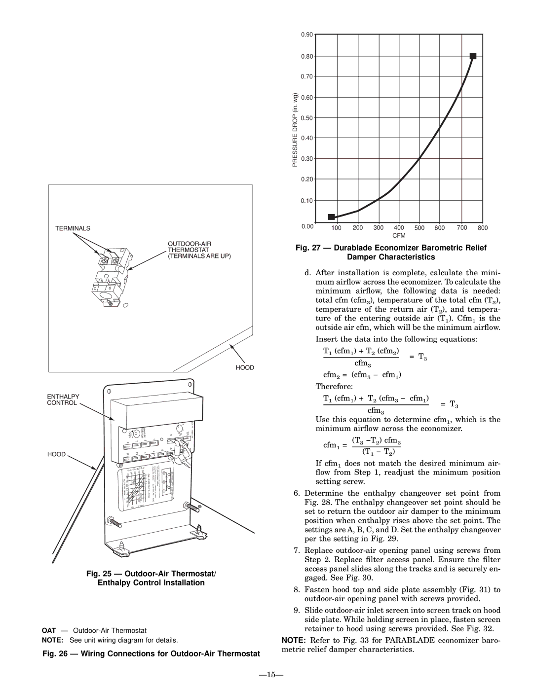
Fig. 25 Ð Outdoor-Air Thermostat/

Enthalpy Control Installation

OAT Ð Outdoor-Air Thermostat

NOTE: See unit wiring diagram for details.

Fig. 26 Ð Wiring Connections for Outdoor-Air Thermostat

Use this equation to determine cfm1, which is the minimum air¯ow across the economizer.

cfm1 = (T3 −T2) cfm3 (T1 − T2)

If cfm1 does not match the desired minimum air- ¯ow from Step 1, readjust the minimum position setting screw.

6.Determine the enthalpy changeover set point from Fig. 28. The enthalpy changeover set point should be set to return the outdoor air damper to the minimum position when enthalpy rises above the set point. The settings are A, B, C, and D. Set the enthalpy changeover per the setting in Fig. 29.

7.Replace outdoor-air opening panel using screws from Step 2. Replace ®lter access panel. Ensure the ®lter access panel slides along the tracks and is securely en- gaged. See Fig. 30.

8.Fasten hood top and side plate assembly (Fig. 31) to outdoor-air opening panel with screws provided.

9.Slide outdoor-air inlet screen into screen track on hood side plate. While holding screen in place, fasten screen retainer to hood using screws provided. See Fig. 32.

NOTE: Refer to Fig. 33 for PARABLADE economizer baro- metric relief damper characteristics.

Ð15Ð

Page 15
Image 15
Bryant 558D installation instructions Outdoor-Air Thermostat Enthalpy Control Installation

558D specifications

The Bryant 558D represents a leading-edge model in the realm of advanced heating, ventilation, and air conditioning (HVAC) systems. Designed for both residential and light commercial applications, this unit brings together efficiency, performance, and reliability, making it a go-to choice for homeowners and contractors alike.

One of the standout features of the Bryant 558D is its high-efficiency rating. With SEER (Seasonal Energy Efficiency Ratio) ratings that can reach up to 18, it allows homeowners to enjoy significant savings on electricity bills while maintaining a comfortable indoor environment. The system is powered by advanced compressors that ensure optimal performance across various climate conditions, providing consistent cooling and heating as needed.

In terms of technology, the Bryant 558D incorporates a two-stage cooling system, which allows for better temperature control and humidity management. This technology enhances comfort by preventing the system from frequently starting and stopping, thus reducing wear and tear while extending the unit's lifespan. The variable-speed blower motor further contributes to this efficiency by adjusting its speed to meet the precise needs of the space, ensuring optimal air distribution and comfort.

Durability is another hallmark of the Bryant 558D. The unit is built with high-quality materials, including a galvanized steel cabinet coated with a sleek, weather-resistant finish that protects against rust and environmental wear. Its compact design makes installation seamless, allowing it to fit into various spaces without significant modifications.

The Bryant 558D also features smart technology compatibility, allowing users to integrate it with modern home automation systems. This connectivity provides homeowners with remote control capabilities, enabling them to regulate their home’s temperature via smartphone applications. This not only adds to convenience but also supports energy management strategies, as users can adjust settings based on occupancy and lifestyle patterns.

Finally, noise levels have been an important consideration in the design of the Bryant 558D. With innovative sound-dampening features, the unit operates quietly, making it an ideal choice for residential areas where noise sensitivity is paramount.

Overall, the Bryant 558D stands out as a sophisticated solution for heating and cooling needs, combining energy efficiency, advanced technology, durability, and user-friendly features. It is an excellent investment for those looking to enhance their home comfort while also being mindful of energy consumption.