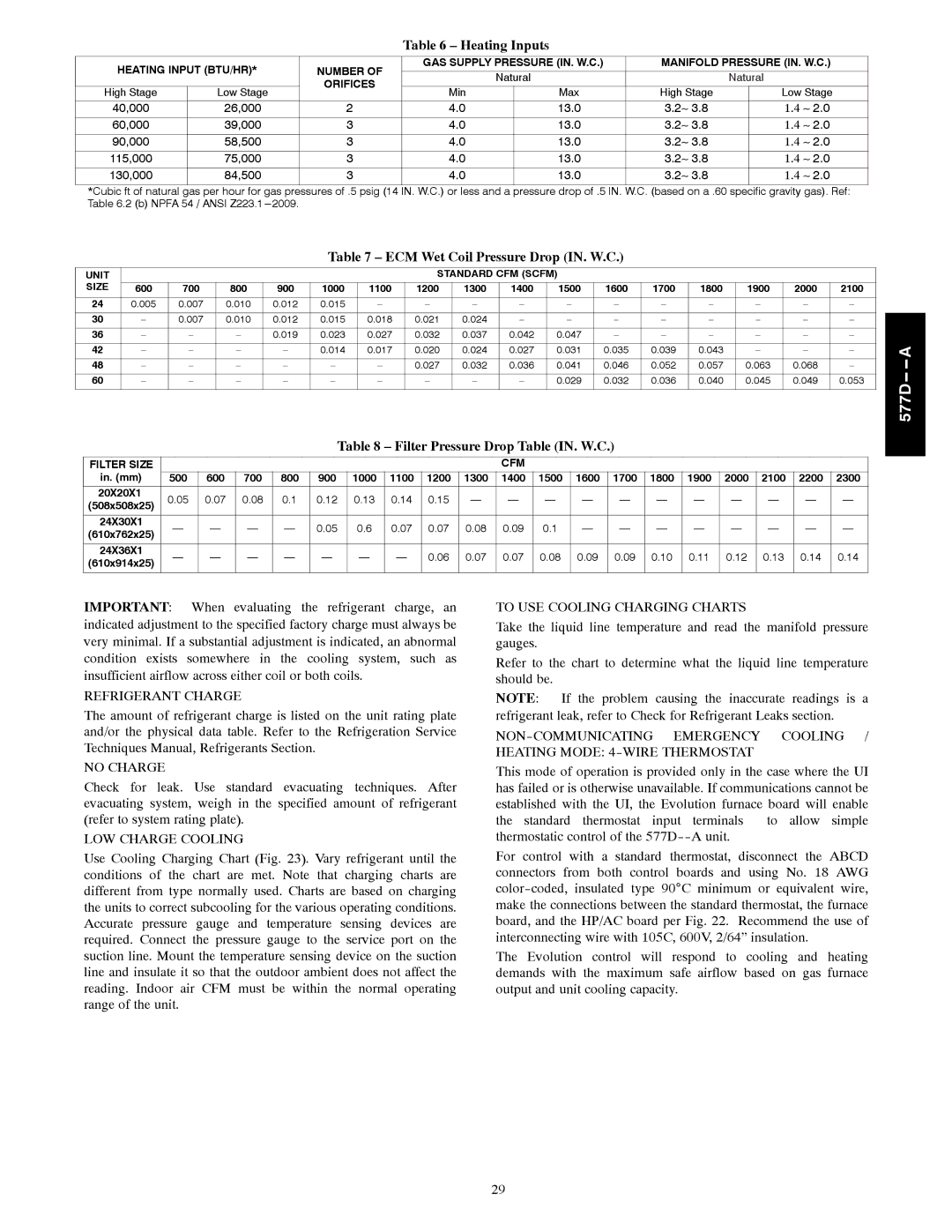
Table 6 – Heating Inputs

HEATING INPUT (BTU/HR)*


NUMBER OF

GAS SUPPLY PRESSURE (IN. W.C.)

MANIFOLD PRESSURE (IN. W.C.)


Natural


Natural


ORIFICES


High Stage

Low Stage


Min

Max

High Stage


Low Stage


40,000

26,000

2

4.0

13.0

3.23.8


1.4 2.0


60,000

39,000

3

4.0

13.0

3.23.8


1.4 2.0

90,000

58,500

3

4.0

13.0

3.23.8


1.4 2.0

115,000

75,000

3

4.0

13.0

3.23.8


1.4 2.0


130,000

84,500

3

4.0

13.0

3.23.8


1.4 2.0

*Cubic ft of natural gas per hour for gas pressures of .5 psig (14 IN. W.C.) or less and a pressure drop of .5 IN. W.C. (based on a .60 specific gravity gas). Ref: Table 6.2 (b) NPFA 54 / ANSI Z223.1---2009.

Table 7 – ECM Wet Coil Pressure Drop (IN. W.C.)

UNIT


STANDARD CFM (SCFM)


SIZE


600

700

800

900

1000

1100

1200

1300

1400

1500

1600

1700

1800

1900

2000

2100


24

0.005

0.007

0.010

0.012

0.015


30

0.007

0.010

0.012

0.015

0.018

0.021

0.024


36

0.019

0.023

0.027

0.032

0.037

0.042

0.047

42

0.014

0.017

0.020

0.024

0.027

0.031

0.035

0.039

0.043

48

0.027

0.032

0.036

0.041

0.046

0.052

0.057

0.063

0.068

60

0.029

0.032

0.036

0.040

0.045

0.049

0.053


Table 8 – Filter Pressure Drop Table (IN. W.C.)

FILTER SIZE


CFM


in. (mm)

500

600

700

800

900

1000

1100

1200

1300

1400

1500

1600

1700

1800

1900

2000

2100

2200

2300

20X20X1

0.05

0.07

0.08

0.1

0.12

0.13

0.14

0.15

(508x508x25)


24X30X1

0.05

0.6

0.07

0.07

0.08

0.09

0.1

(610x762x25)


24X36X1

0.06

0.07

0.07

0.08

0.09

0.09

0.10

0.11

0.12

0.13

0.14

0.14

(610x914x25)


577D-- -- A

IMPORTANT: When evaluating the refrigerant charge, an indicated adjustment to the specified factory charge must always be very minimal. If a substantial adjustment is indicated, an abnormal condition exists somewhere in the cooling system, such as insufficient airflow across either coil or both coils.

REFRIGERANT CHARGE

The amount of refrigerant charge is listed on the unit rating plate and/or the physical data table. Refer to the Refrigeration Service Techniques Manual, Refrigerants Section.

NO CHARGE

Check for leak. Use standard evacuating techniques. After evacuating system, weigh in the specified amount of refrigerant (refer to system rating plate).

LOW CHARGE COOLING

Use Cooling Charging Chart (Fig. 23). Vary refrigerant until the conditions of the chart are met. Note that charging charts are different from type normally used. Charts are based on charging the units to correct subcooling for the various operating conditions. Accurate pressure gauge and temperature sensing devices are required. Connect the pressure gauge to the service port on the suction line. Mount the temperature sensing device on the suction line and insulate it so that the outdoor ambient does not affect the reading. Indoor air CFM must be within the normal operating range of the unit.

TO USE COOLING CHARGING CHARTS

Take the liquid line temperature and read the manifold pressure gauges.

Refer to the chart to determine what the liquid line temperature should be.

NOTE: If the problem causing the inaccurate readings is a refrigerant leak, refer to Check for Refrigerant Leaks section.

NON-COMMUNICATING EMERGENCY COOLING / HEATING MODE: 4-WIRE THERMOSTAT

This mode of operation is provided only in the case where the UI has failed or is otherwise unavailable. If communications cannot be established with the UI, the Evolution furnace board will enable the standard thermostat input terminals to allow simple thermostatic control of the 577D--A unit.

For control with a standard thermostat, disconnect the ABCD connectors from both control boards and using No. 18 AWG color-coded, insulated type 90°C minimum or equivalent wire, make the connections between the standard thermostat, the furnace board, and the HP/AC board per Fig. 22. Recommend the use of interconnecting wire with 105C, 600V, 2/64” insulation.

The Evolution control will respond to cooling and heating demands with the maximum safe airflow based on gas furnace output and unit cooling capacity.

29

Page 29
Image 29
Bryant 577D----A Heating Inputs, ECM Wet Coil Pressure Drop IN. W.C, Filter Pressure Drop Table IN. W.C

577D----A specifications

The Bryant 577D----A is a highly regarded model in the HVAC industry, representing a blend of efficiency, performance, and advanced technology. This heating and cooling unit is designed to cater to a variety of residential and light commercial applications, making it a versatile choice for consumers looking to enhance their indoor climate control systems.

One of the standout features of the Bryant 577D----A is its impressive energy efficiency rating. With a Seasonal Energy Efficiency Ratio (SEER) typically exceeding 14, this model is engineered to reduce energy consumption, helping homeowners lower their utility bills while minimizing environmental impact. The unit also employs a two-stage cooling system, which not only improves comfort by maintaining more consistent temperatures but also provides enhanced dehumidification during hotter months.

The technology used in the Bryant 577D----A is noteworthy. The unit incorporates a variable-speed compressor that adapts to the specific cooling or heating needs of the space, ensuring optimal performance at all times. This advanced feature not only contributes to energy savings but also allows for quieter operation compared to single-stage systems. The inclusion of a smart thermostat integration further enhances convenience, enabling users to manage their HVAC system remotely and optimize settings according to their schedules.

Additional characteristics of the Bryant 577D----A include a durable construction designed to withstand various environmental conditions. The cabinet is made from quality materials that protect against corrosion and other factors that could affect the unit's longevity. Furthermore, the unit operates quietly, thanks to sound-dampening technologies, which is a significant advantage for residential areas where noise can be a concern.

Maintenance is also simplified with the Bryant 577D----A, as it is equipped with self-diagnostics for easy troubleshooting. This feature alerts users to potential issues before they escalate, promoting efficient operation and prolonging the lifespan of the system.

In conclusion, the Bryant 577D----A stands out as a superior choice for those seeking reliability and efficiency in their HVAC solutions. With its energy-efficient operation, advanced technologies, and robust construction, it serves as a valuable investment for homeowners committed to comfort and sustainability.