SERVICE (cont.)
AUGER DRIVE COMPONENTS (cont.)
14.Install hopper assy (21) in the dispenser by sliding hopper assy in the guides on the hopper support plate (20) until the slot in the bottom rear the hopper seats against the shoulder screw (19) in the hopper support plate.
Auger Drive Motor (Refer to Fig. 2)
1.Remove hopper assy (21) and set aside for reas- sembly.
2.Remove the the four
3.Remove the four
(17)to the rear of the auger motor mounting panel
(15).
4.Disconnect the wires from the auger motor (17) to be removed.
5.Remove auger motor mounting bracket (16), au- ger motor (17) and dust seal (18) as an assembly.
6.Remove dust seal (18) from auger motor (17).
7.Remove the four
8.Remove auger motor and discard.
9.Using four
(17)on mounting bracket (16).
10.Install dust seal (18) on auger motor shaft.
11.Using four
12.Reconnect the wires to the terminals on the bot- tom of the auger motor.
13.Install hopper support plate (20) and hopper as- sembly (21).
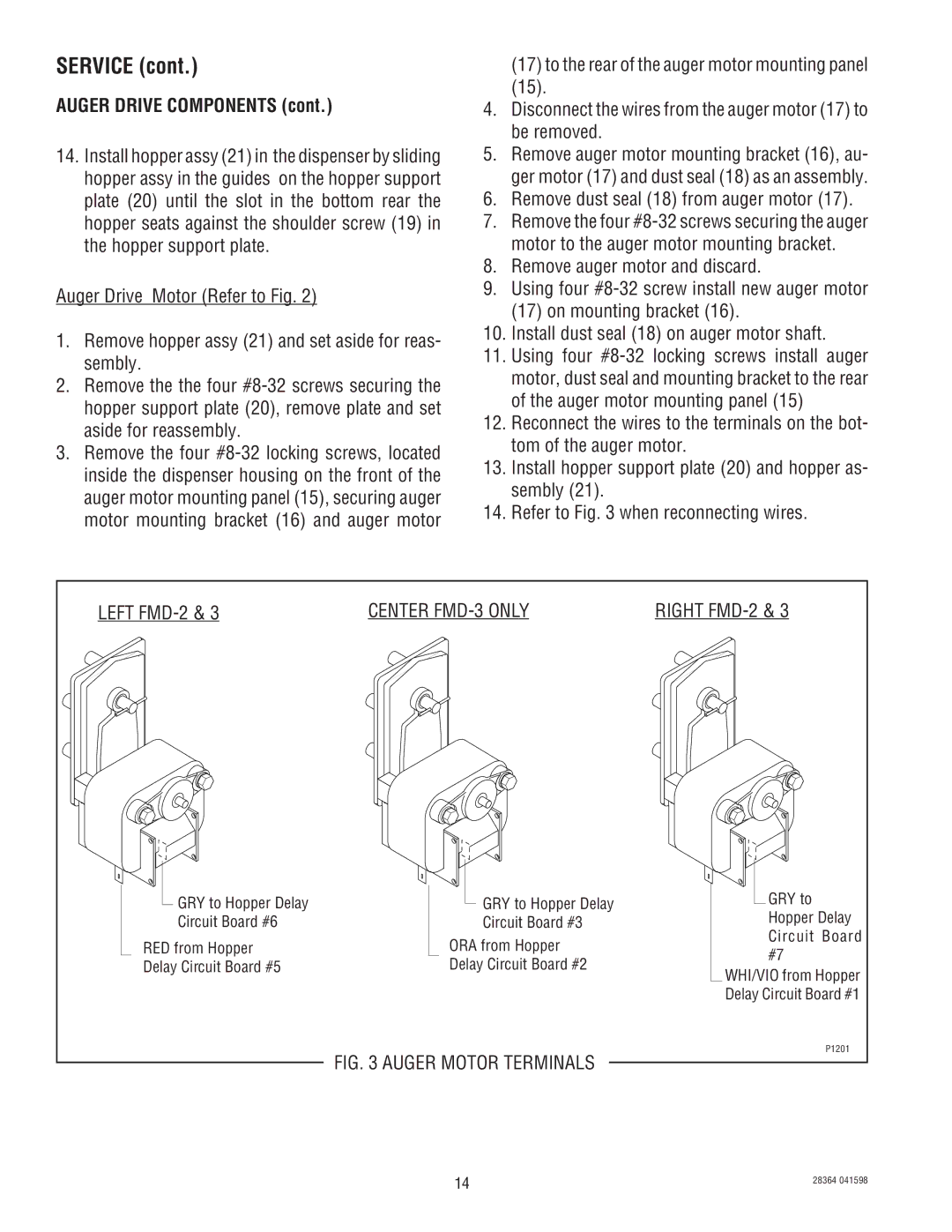
14.Refer to Fig. 3 when reconnecting wires.
LEFT | CENTER | RIGHT | |
GRY to Hopper Delay | GRY to Hopper Delay | GRY to | |
Circuit Board #6 | Circuit Board #3 | Hopper Delay | |
RED from Hopper | ORA from Hopper | Circuit Board | |
#7 | |||
Delay Circuit Board #5 | Delay Circuit Board #2 | ||
WHI/VIO from Hopper | |||
|
| ||
|
| Delay Circuit Board #1 | |
| FIG. 3 AUGER MOTOR TERMINALS | P1201 | |
|
| ||
| 14 | 28364 041598 | |
|
|