SERVICE (cont.)
CONTROL THERMOSTAT
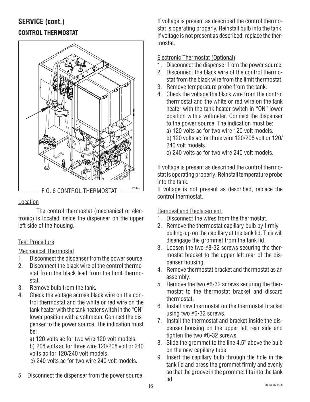
FIG. 6 CONTROL THERMOSTAT | P1445 |
| |
Location |
|
The control thermostat (mechanical or elec- tronic) is located inside the dispenser on the upper left side of the housing.
Test Procedure
Mechanical Thermostat
1.Disconnect the dispenser from the power source.
2.Disconnect the black wire of the control thermo- stat from the black lead from the limit thermo- stat.
3.Remove bulb from the tank.
4.Check the voltage across black wire on the con- trol thermostat and the white or red wire on the tank heater with the tank heater switch in the “ON” lower position with a voltmeter. Connect the dis- penser to the power source. The indication must be:
a)120 volts ac for two wire 120 volt models.
b)208 volts ac for three wire 120/208 volt or 240 volts ac for 120/240 volt models.
c)240 volts ac for two wire 240 volt models.
5.Disconnect the dispenser from the power source.
If voltage is present as described the control thermo- stat is operating properly. Reinstall bulb into the tank. If voltage is not present as described, replace the ther- mostat.
Electronic Thermostat (Optional)
1.Disconnect the dispenser from the power source.
2.Disconnect the black wire of the control thermo- stat from the black wire from the limit thermostat.
3.Remove temperature probe from the tank.
4.Check the voltage the black wire from the control thermostat and the white or red wire on the tank heater with the tank heater switch in “ON” lower position with a voltmeter. Connect the dispenser to the power source. The indication must be:
a)120 volts ac for two wire 120 volt models.
b)120 volts ac for three wire 120/208 volt or 120/ 240 volt models.
c)240 volts ac for two wire 240 volt models.
If voltage is present as described the control thermo- stat is operating properly. Reinstall temperature probe into the tank.
If voltage is not present as described, replace the control thermostat.
Removal and Replacement.
1.Disconnect the wires from the thermostat.
2.Remove the thermostat capillary bulb by firmly
3.Loosen the two
4.Remove thermostat bracket and thermostat as an assembly.
5.Remove the two
6.Install new thermostat on the thermostat bracket using two
7.Install the thermostat and bracket inside the dis- penser housing on the upper left rear side and tighten the two
8.Slide the grommet to the line 4.5” above the bulb on the new capillary tube.
9.Insert the capillary bulb through the hole in the tank lid and press the grommet firmly and evenly so that the groove in the grommet fits into the tank lid.
16 | 28364 071598 |
|