SERVICE (cont.)
DISPENSE SWITCH (cont.)
6.Check for continuity across the terminals on the dispense switch with the switch in the “ON” pressed position. Continuity must not be present when the switch is in the “OFF” released posi- tion.
If continuity is present as described, reconnect the connector to the door interconnect wiring harness, the switch is operating properly.
If continuity is not present as described, replace the switch.
Removal and Replacement
1.Open the dispenser door.
2.Remove the five
3.Disconnect the wires on the dispense switch to be removed from the door interconnect wiring harness.
4.Compress the clips inside the door on the dis- pense switch and gently push the switch through the opening.
5.Push new switch into the opening and spread the clips to hold the switch in the door.
6.Reconnect the wires to the dispense switch from door interconnect wiring harness.
7.Reinstall the door bottom cover using five
8.Refer to Fig. 9 when reinstalling wires.
| BLK |
|
| RED/BLK |
|
| BLK |
|
| RED/WHI |
|
BLK |
|
|
RED | RIGHT |
|
| FMD 2 & 3 | |
| CENTER |
|
|
| |
| LEFT |
|
| FMD 2 &3 |
|
| FIG. 9 DISPENSE SWITCH TERMINALS | P1449 |
FAN |
|
FIG. 10 FAN | P1436 |
|
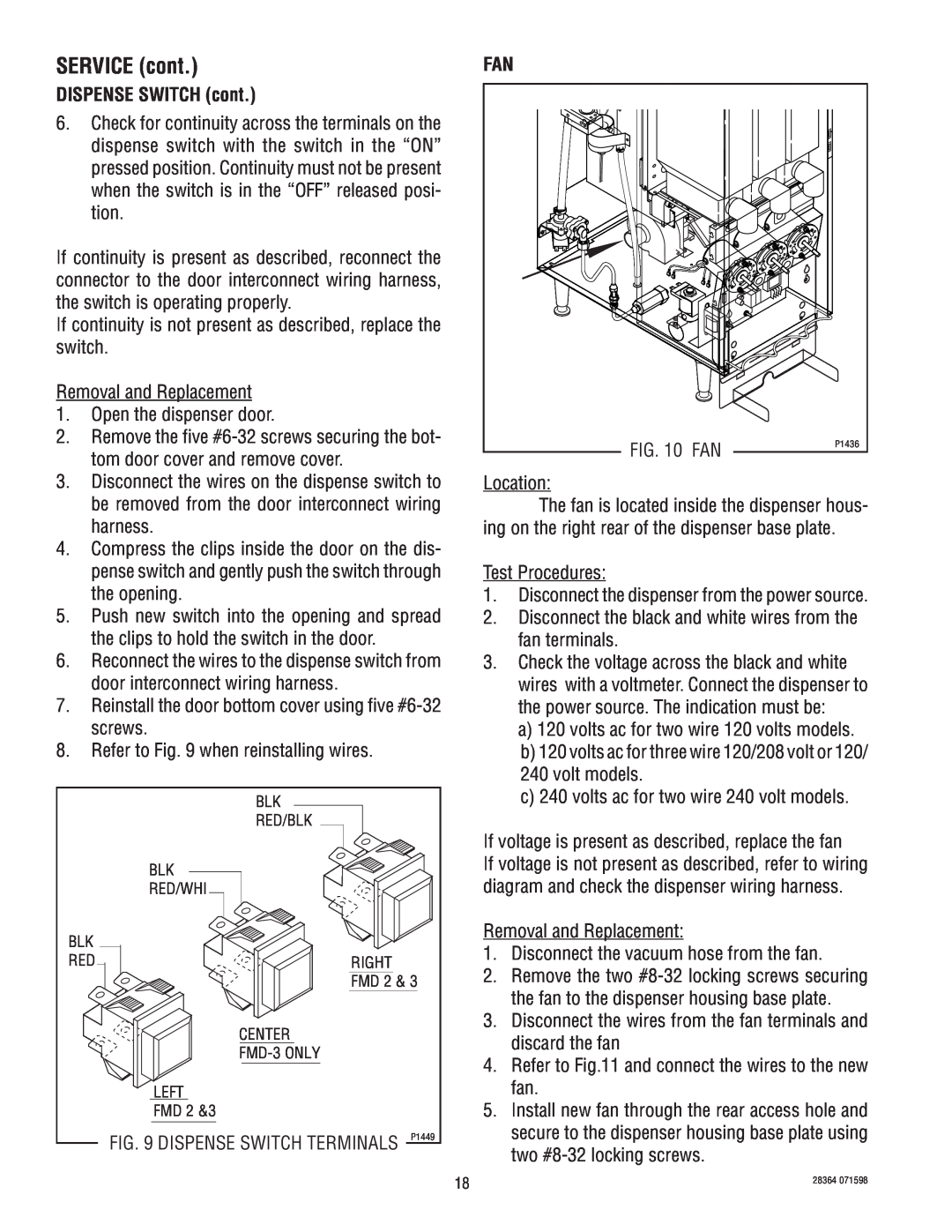
Location:
The fan is located inside the dispenser hous- ing on the right rear of the dispenser base plate.
Test Procedures:
1.Disconnect the dispenser from the power source.
2.Disconnect the black and white wires from the fan terminals.
3.Check the voltage across the black and white wires with a voltmeter. Connect the dispenser to the power source. The indication must be:
a)120 volts ac for two wire 120 volts models.
b)120 volts ac for three wire 120/208 volt or 120/ 240 volt models.
c)240 volts ac for two wire 240 volt models.
If voltage is present as described, replace the fan
If voltage is not present as described, refer to wiring diagram and check the dispenser wiring harness.
Removal and Replacement:
1.Disconnect the vacuum hose from the fan.
2.Remove the two
3.Disconnect the wires from the fan terminals and discard the fan
4.Refer to Fig.11 and connect the wires to the new fan.
5.Install new fan through the rear access hole and secure to the dispenser housing base plate using two
18 | 28364 071598 |
|