Cylinder No.
7EN0448
Push rod | Guide B | Guide A: |
|
| |
|
| 17.9 mm |
REMOVAL SERVICE POINTS
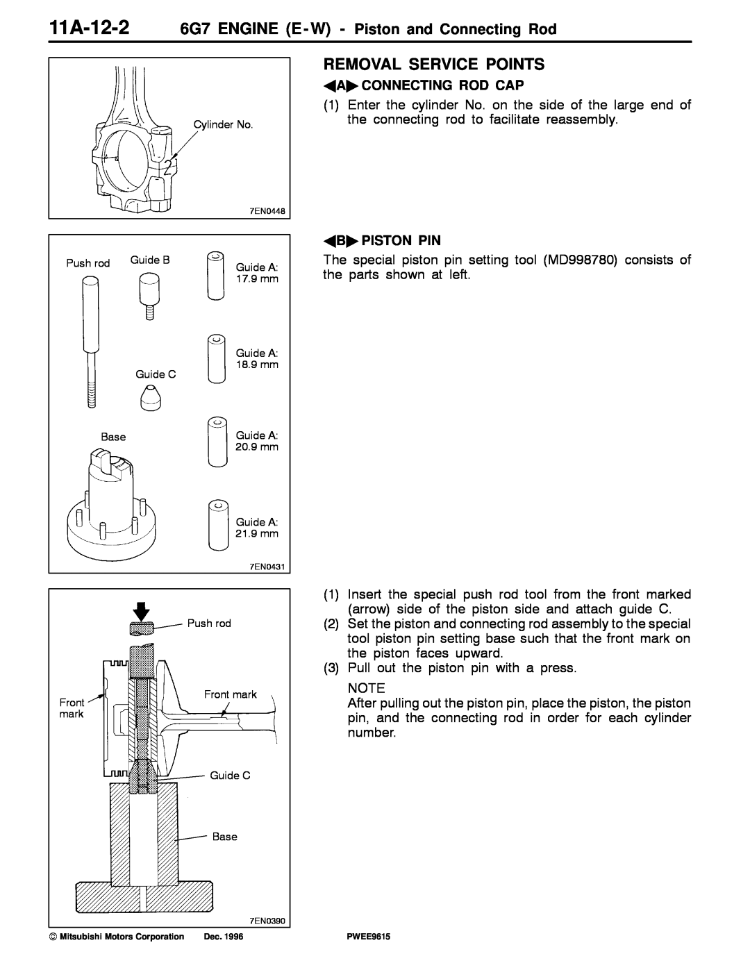
AA" CONNECTING ROD CAP
(1)Enter the cylinder No. on the side of the large end of the connecting rod to facilitate reassembly.
AB" PISTON PIN
The special piston pin setting tool (MD998780) consists of the parts shown at left.
Guide C
Guide A: 18.9 mm
Base | Guide A: |
| 20.9 mm |
Guide A: 21.9 mm
7EN0431
Push rod
(1) | Insert the special push rod tool from the front marked |
| (arrow) side of the piston side and attach guide C. |
(2) | Set the piston and connecting rod assembly to the special |
| tool piston pin setting base such that the front mark on |
| the piston faces upward. |
(3) | Pull out the piston pin with a press. |
| NOTE |
Front mark
Front mark
Guide C
Base
7EN0390
After pulling out the piston pin, place the piston, the piston |
pin, and the connecting rod in order for each cylinder |
number. |
E Mitsubishi Motors Corporation | Dec. 1996 |
PWEE9615