SERVICE (cont.)
BREW TIMER (Early Models)(cont.)
Removal and Replacement:
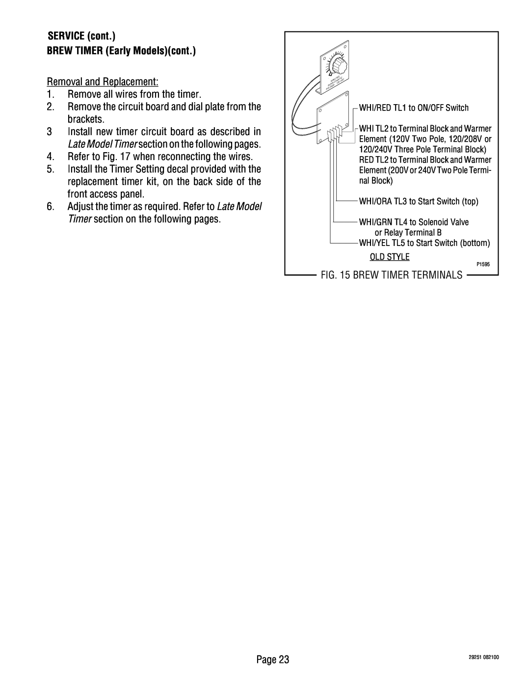
1.Remove all wires from the timer.
2.Remove the circuit board and dial plate from the brackets.
3Install new timer circuit board as described in
Late Model Timer section on the following pages.
4.Refer to Fig. 17 when reconnecting the wires.
5.Install the Timer Setting decal provided with the replacement timer kit, on the back side of the front access panel.
6.Adjust the timer as required. Refer to Late Model Timer section on the following pages.
. |
|
|
| U | TE | S | IC |
|
| MIN |
| AT |
| C | |||
|
| 0 | VA |
| ||||
| UN | N | 12 |
|
| |||
B | 20 | - |
|
|
|
| ||
26 |
|
|
|
|
|
| ||
P/N |
|
|
|
|
|
|
| |
|
|
|
|
|
|
|
| |
WHI/RED TL1 to ON/OFF Switch
WHI TL2 to Terminal Block and Warmer Element (120V Two Pole, 120/208V or 120/240V Three Pole Terminal Block)
RED TL2 to Terminal Block and Warmer Element (200V or 240V Two Pole Termi- nal Block)
WHI/ORA TL3 to Start Switch (top)
WHI/GRN TL4 to Solenoid Valve or Relay Terminal B
WHI/YEL TL5 to Start Switch (bottom)
OLD STYLE
P1595
FIG. 15 BREW TIMER TERMINALS
Page 23 | 29251 082100 |
|
