Heat Anticipator in Thermostat should be set to match the requirements of the control to which it is connected. See Table 4. If system tends to overheat above the thermostat's temperature setting, reduce heat anticipator setting by .1 or .2 amps. If system tends to short cycle without reaching desired room temperature, increase heat anticipator setting by .1 or .2 amps.
16.Install electric wiring in accordance with National Electric Code or the Canadian Electrical Code and local regulations. See Figures 11 through 16 for applicable wiring diagram. A separate electrical circuit must be run from the main electrical service with an
For zone valve wiring, a separate 24V transformer is required rather than attempting to use the boiler mounted control. Consult zone valve manufacturer for assistance.
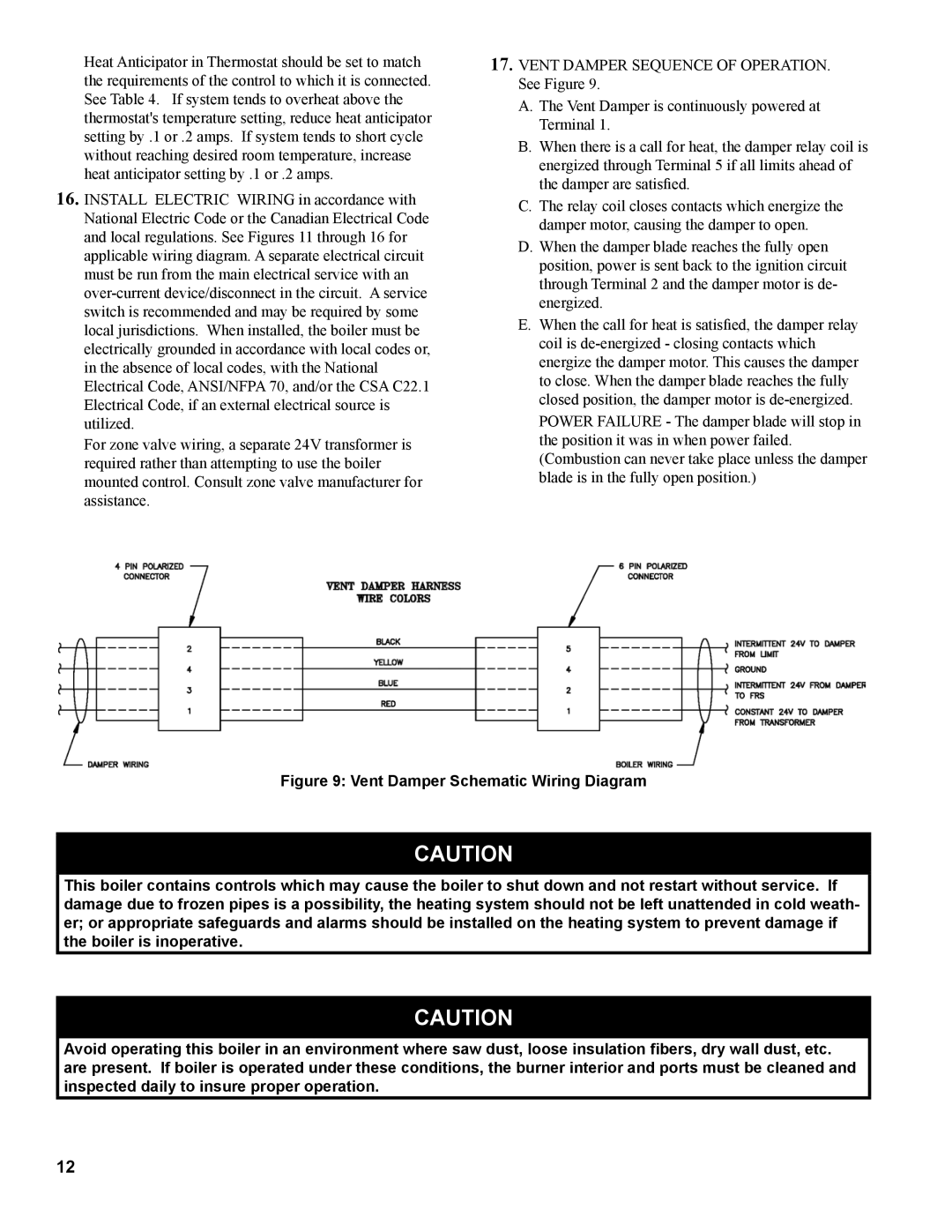
17. Vent Damper Sequence of Operation. See Figure 9.
A.The Vent Damper is continuously powered at Terminal 1.
B.When there is a call for heat, the damper relay coil is energized through Terminal 5 if all limits ahead of the damper are satisfied.
C.The relay coil closes contacts which energize the damper motor, causing the damper to open.
D.When the damper blade reaches the fully open position, power is sent back to the ignition circuit through Terminal 2 and the damper motor is de- energized.
E.When the call for heat is satisfied, the damper relay coil is
Power Failure - The damper blade will stop in the position it was in when power failed. (Combustion can never take place unless the damper blade is in the fully open position.)
Figure 9: Vent Damper Schematic Wiring Diagram
CAUTION
This boiler contains controls which may cause the boiler to shut down and not restart without service. If damage due to frozen pipes is a possibility, the heating system should not be left unattended in cold weath- er; or appropriate safeguards and alarms should be installed on the heating system to prevent damage if the boiler is inoperative.
CAUTION
Avoid operating this boiler in an environment where saw dust, loose insulation fibers, dry wall dust, etc. are present. If boiler is operated under these conditions, the burner interior and ports must be cleaned and inspected daily to insure proper operation.
12