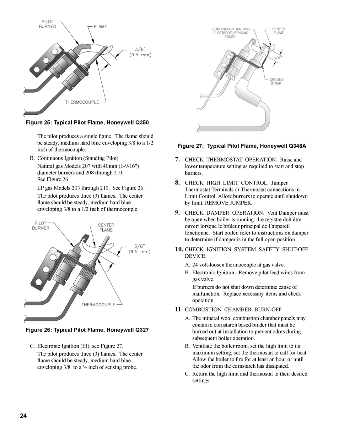
Figure 25: Typical Pilot Flame, Honeywell Q350
The pilot produces a single flame. The flame should be steady, medium hard blue enveloping 3/8 to a 1/2 inch of thermocouple.
B.Continuous Ignition (Standing Pilot)
Natural gas Models 207 with 40mm
See Figure 26.
LP gas Models 203 through 210. See Figure 26.
The pilot produces three (3) flames. The center flame should be steady, medium hard blue enveloping 3/8 to a 1/2 inch of thermocouple.
Figure 26: Typical Pilot Flame, Honeywell Q327
C.Electronic Ignition (EI), see Figure 27.
The pilot produces three (3) flames. The center flame should be steady, medium hard blue enveloping 3/8 to a ½ inch of sensing probe.
Figure 27: Typical Pilot Flame, Honeywell Q348A
7.Check thermostat operation. Raise and lower temperature setting as required to start and stop burners.
8.Check high limit control. Jumper Thermostat Terminals or Thermostat connections in Limit Control. Allow burners to operate until shutdown by limit. Remove jumper.
9.CHECK DAMPER OPERATION. Vent Damper must be open when boiler is running. Le registre doit être ouvert lorsque le brûleur principal de l’appareil fonctionne. Start boiler, refer to instructions on damper to determine if damper is in the full open position.
10.CHECK IGNITION SYSTEM SAFETY SHUT-OFF DEVICE.
A.24
B.Electronic Ignition - Remove pilot lead wires from gas valve.
If burners do not shut down determine cause of malfunction. Replace necessary items and check operation.
11. COMBUSTION CHAMBER BURN-OFF
A.The mineral wool combustion chamber panels may contain a cornstarch based binder that must be burned out at installation to prevent odors during subsequent boiler operation.
B.Ventilate the boiler room, set the high limit to its maximum setting, set the thermostat to call for heat.
Allow the boiler to fire for at least an hour or until the odor from the cornstarch has dissipated.
C.Return the high limit and thermostat to their desired settings.
24