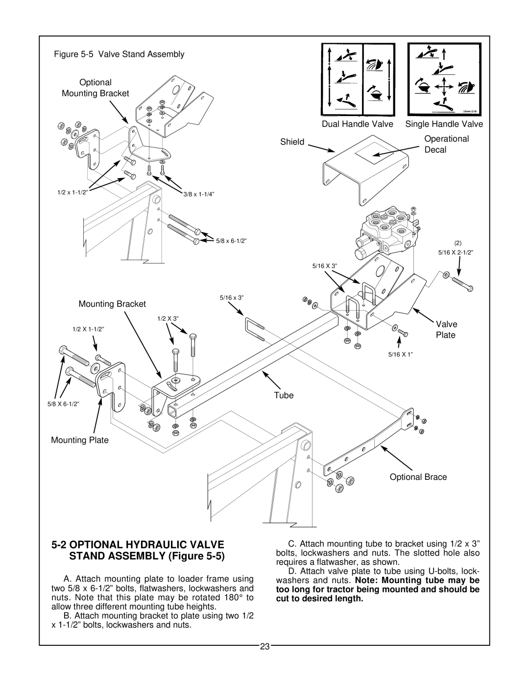
Figure 5-5 Valve Stand Assembly
Optional
Mounting Bracket
|
| Dual Handle Valve Single Handle Valve | ||||
|
|
|
|
| ||
|
|
|
|
|
| |
|
|
|
| Operational |
| |
Shield | ||||||
|
|
| Decal |
| ||
|
|
|
|
| ||
| ||||||
|
|
|
|
|
| |
|
|
|
|
|
| |
1/2 x | 3/8 x |
|
![]()
![]()
![]()
![]() 5/8 x
5/8 x
5/16 x 3”
Mounting Bracket
1/2 X 3”
1/2 X
5/8 X
Mounting Plate
5-2 OPTIONAL HYDRAULIC VALVE STAND ASSEMBLY (Figure 5-5)
A. Attach mounting plate to loader frame using two 5/8 x
B. Attach mounting bracket to plate using two 1/2 x
(2)
5/16 X
5/16 X 3”
Valve
Plate
5/16 X 1”
Tube
Optional Brace
C. Attach mounting tube to bracket using 1/2 x 3” bolts, lockwashers and nuts. The slotted hole also requires a flatwasher, as shown.
D. Attach valve plate to tube using
23