Introduction
1.3 CHASSIS OVERVIEW
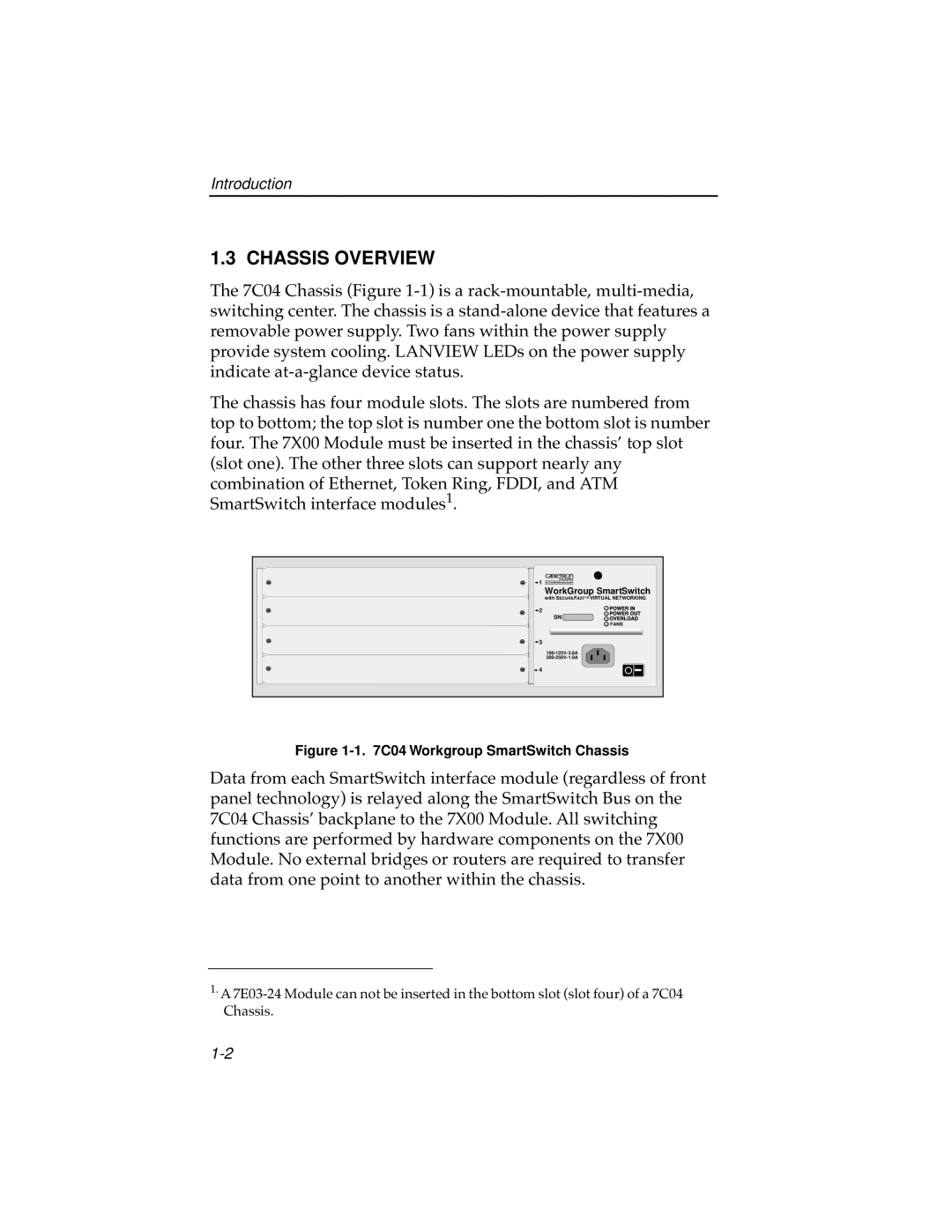
The 7C04 Chassis (Figure
The chassis has four module slots. The slots are numbered from top to bottom; the top slot is number one the bottom slot is number four. The 7X00 Module must be inserted in the chassis’ top slot (slot one). The other three slots can support nearly any combination of Ethernet, Token Ring, FDDI, and ATM SmartSwitch interface modules1.
1 | WorkGroup SmartSwitch |
| |
| with SECUREFAST™ VIRTUAL NETWORKING |
2 |
|
| SN |
| FANS |
3 |
|
| |
| |
4 | I |
|
Figure 1-1. 7C04 Workgroup SmartSwitch Chassis
Data from each SmartSwitch interface module (regardless of front panel technology) is relayed along the SmartSwitch Bus on the 7C04 Chassis’ backplane to the 7X00 Module. All switching functions are performed by hardware components on the 7X00 Module. No external bridges or routers are required to transfer data from one point to another within the chassis.
1.A