Cabletron Systems F3 user manual 2 AUI Connection

Models: F3

1 44
Download 44 pages 168 b
Page 24
Image 24
Figure 3-2 AUI Connection

CHAPTER 3: INSTALLATION

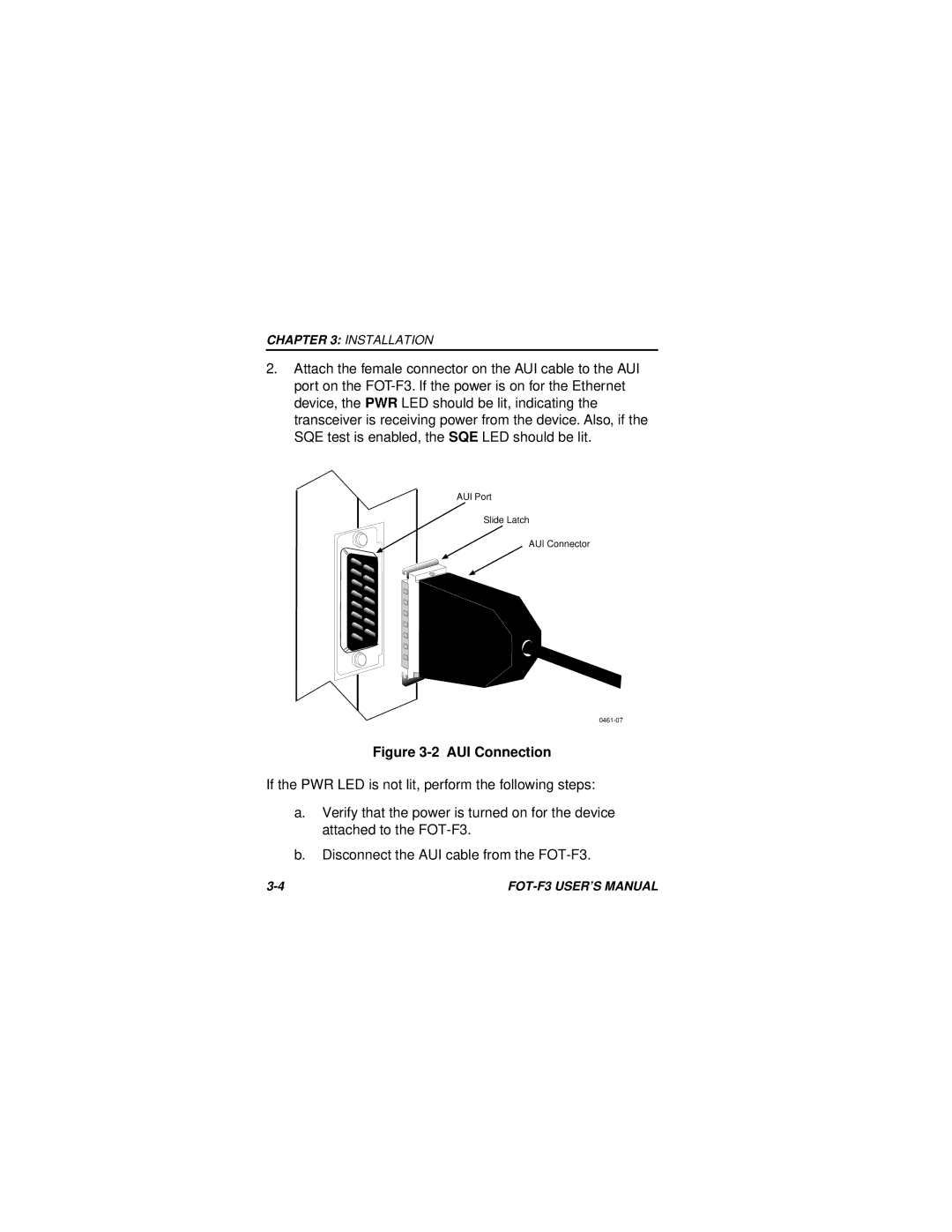
2.Attach the female connector on the AUI cable to the AUI port on the FOT-F3. If the power is on for the Ethernet device, the PWR LED should be lit, indicating the transceiver is receiving power from the device. Also, if the SQE test is enabled, the SQE LED should be lit.

AUI Port

Slide Latch

AUI Connector

0461-07

Figure 3-2 AUI Connection

If the PWR LED is not lit, perform the following steps:

a.Verify that the power is turned on for the device attached to the FOT-F3.

b.Disconnect the AUI cable from the FOT-F3.

3-4

FOT-F3 USER’S MANUAL

Page 24
Image 24
Cabletron Systems F3 user manual 2 AUI Connection