USING LANVIEW
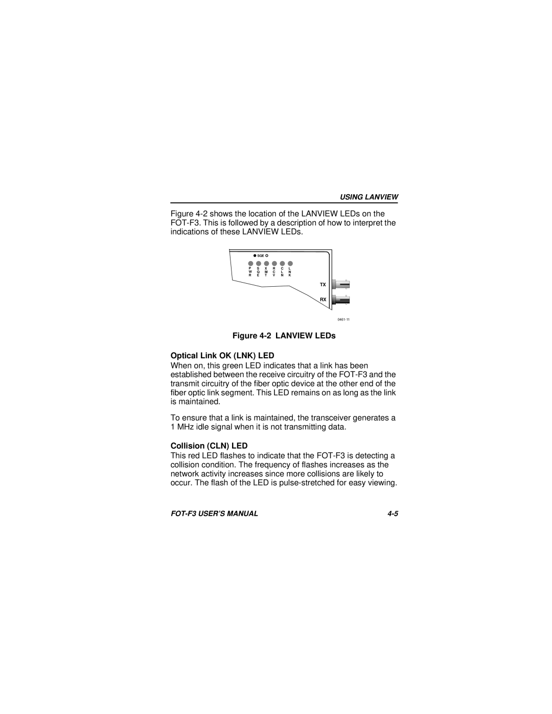
Figure 4-2 shows the location of the LANVIEW LEDs on the FOT-F3. This is followed by a description of how to interpret the indications of these LANVIEW LEDs.
| SQE |
|
|
|
|
P | S | X | R | C | L |
W | Q | M | C | L | N |
R | E | T | V | N | K |
|
|
|
|
| TX |
|
|
|
|
| RX |
|
|
|
|
|
Figure 4-2 LANVIEW LEDs
Optical Link OK (LNK) LED
When on, this green LED indicates that a link has been established between the receive circuitry of the
To ensure that a link is maintained, the transceiver generates a 1 MHz idle signal when it is not transmitting data.
Collision (CLN) LED
This red LED flashes to indicate that the
|