FEPIM Specifications
|
|
|
|
|
|
|
|
|
|
|
|
|
|
|
|
| SP |
|
|
| |||
|
|
|
|
|
|
|
|
|
|
|
| Figure |
|
| |
|
| Table | |||||
|
|
|
|
|
|
|
|
Cable Type |
| Worst Case Budget | Typical Budget | ||||
|
|
|
|
|
|
|
|
50/125 µm fiber |
| 6.0 dB |
| 9.0 dB | |||
|
|
|
|
|
|
|
|
62.5/125 µm fiber |
| 9.0 dB |
| 12.0 dB | |||
|
|
|
|
|
|
|
|
100/140 µm fiber |
| 15.0 dB |
| 18.0 dB | |||
|
|
|
|
|
|
|
|
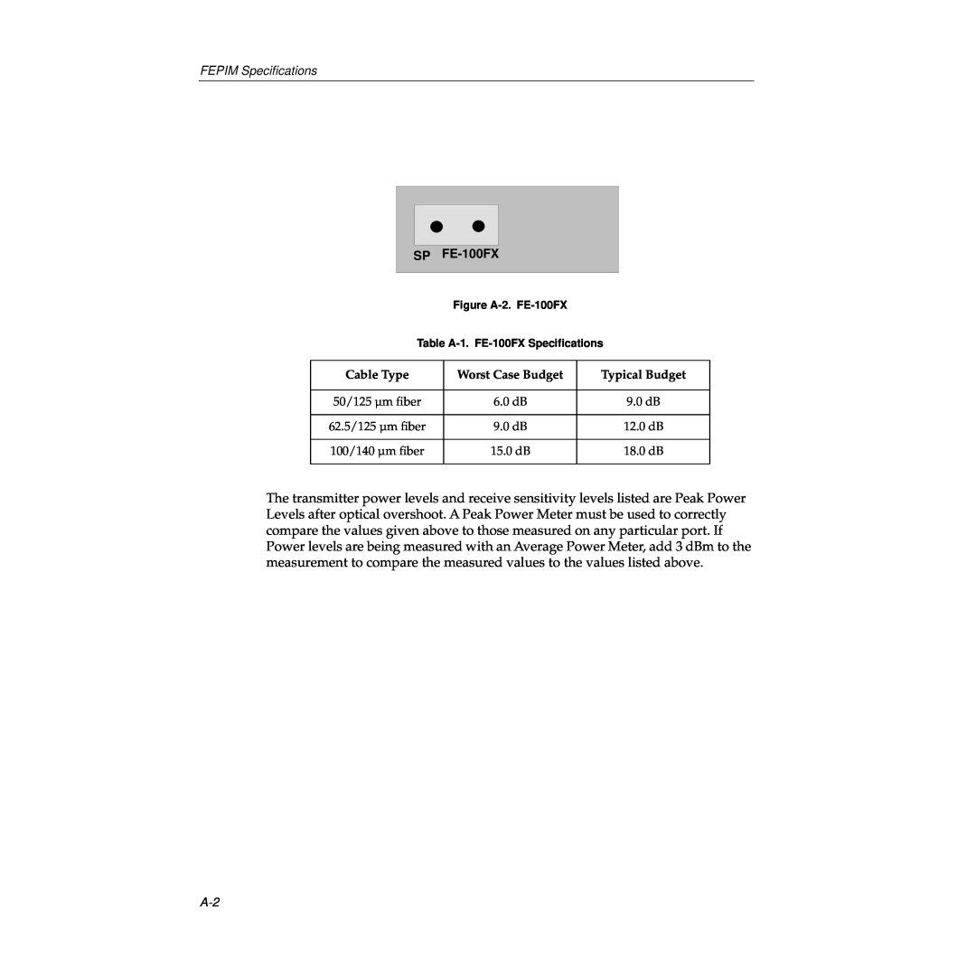
The transmitter power levels and receive sensitivity levels listed are Peak Power Levels after optical overshoot. A Peak Power Meter must be used to correctly compare the values given above to those measured on any particular port. If Power levels are being measured with an Average Power Meter, add 3 dBm to the measurement to compare the measured values to the values listed above.
