Operating Instructions and Parts Manual
Modelo CHN50399
Operating The Nailer
LUBRICATION
This nailer requires lubrication before using the nailer for the first time and before each use. If an inline oiler is used, manual lubrication through the air inlet is not required on a daily basis.
The work surface
can become damaged by excessive lubrication. Proper lubrication is the owner’s responsibility. Failure to lubricate the nailer properly will dramatically shorten the life of the nailer and void your warranty.
1.Disconnect the air supply from the nailer
to add lubricant.
2.Turn the nailer so the air inlet is facing up.
Place
into air inlet. Do not use detergent oils, oil additives, or
air tool oils which contain solvents. This will damage the nailer’s internal components.
RECOMMENDED HOOKUP
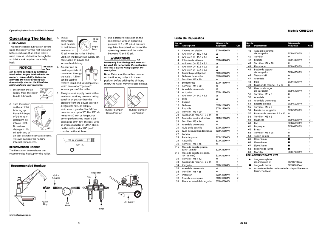
The illustration below shows the recommended hookup for the nailer.
1. The air compressor must be able to maintain a minimum of
70 psi when the nailer is being used. An inadequate air supply can cause a loss of power and inconsistent driving.
2. An oiler can be![]() used to provide oil
used to provide oil ![]()
![]()
![]()
![]()
![]() circulation through
circulation through ![]()
![]() the nailer. A filter
the nailer. A filter ![]()
![]()
![]()
![]() can be used to
can be used to![]() remove liquid and solid impurities which can rust or “gum up” internal parts of the nailer.
remove liquid and solid impurities which can rust or “gum up” internal parts of the nailer.
3.Always use air supply hoses with a minimum working pressure rating equal to or greater than the pressure from the power source if a regulator fails, or 150 psi, whichever is greater. Use 3/8" air hose for runs up to 50'. Use 1/2" air hoses for 50' run or longer. For better performance, install a 3/8" quick plug (1/4" NPT threads) with an inside diameter of .315" (8 mm) on the nailer and a 3/8" quick coupler on the air hose.
150 psi or greater
3/8" I.D.
4.Use a pressure regulator on the compressor, with an operating pressure of 0 - 125 psi. A pressure regulator is required to control the operating pressure of the nailer between 70 and 90 psi.
![]()
![]()
![]() An improperly functioning tool must not be used. Do not actuate the tool unless the tool is placed firmly against the work piece.
An improperly functioning tool must not be used. Do not actuate the tool unless the tool is placed firmly against the work piece.
Note: Make sure the rubber bumper on the flooring nailer is in the up position before adding the air hose, if not, the nailer may cycle (see below).
Rubber Bumper | Rubber Bumper |
Down Position | Up Position |
Lista de Repuestos
No. de |
| Número de |
|
Ref | Descripción | Repuesto | Ctd |
1 | Cabeza del pistón | SX140100AV | 1 |
2 | Anillo en O - 19.2 x 1.8 | ▲ | 1 |
3 | Anillo en O - 15.9 x 1.8 | ▲ | 1 |
4 | Cilindro de válvula | SX140400AV | 1 |
5 | Anillo en O - 42.5 x 5.4 | ▲ | 1 |
6 | Anillo en O - 17.5 x 2.6 | ▲ | 1 |
7 | Anillo en O - 57.4 x 3.5 | ▲ | 1 |
8 | Ensamblaje del pistón | SX140800AV | 1 |
9 | Defensa de caucho | SX140900AV | 1 |
10 | Tornillo - M5 x 20 | ❋ | 1 |
11 | Sombrerete | SX141100AV | 1 |
12 | Tornillo - M4 x 20 | ❋ | 1 |
13 | Arandela de resorte | ❋ | 1 |
14 | Actuador | SX141400AV | 1 |
15 | Anillo en O - 54.2 x 3.5 | ▲ | 1 |
16 | Sello | ▲ | 1 |
17 | Cuerpo | 1 | |
18 | Defensa | SX141800AV | 1 |
19 | Boquilla | SX141900AV | 1 |
20 | Tornillo - M3 x 20 | ❋ | 1 |
21 | Pasador de resorte - 3 x 14 | ❋ | 1 |
22 | Protector contra el polvo | SX142200AV | 1 |
23 | Tornillo - M5 x 14 | ❋ | 1 |
24 | Arandela de resorte | ❋ | 1 |
25 | Guía de la cuchilla | SX142500AV | 1 |
26 | Guía de puntillas dentadas | SX142600AV | 1 |
27 | Zapata | 1 | |
28 | Pata de goma | SX142800AV | 2 |
29 | Casquillo | SX142900AV | 1 |
30 | Tornillo - M6 x 16 | ❋ | 1 |
31a | Placa de zapata gruesa, |
|
|
| 5/16" (8 mm) | SX143100AV | 1 |
31b | Placa de zapata delgada, |
|
|
| 1/4" (6 mm) | SX143200AV | 1 |
32 | Tornillo - M6 x 12 | ❋ | 1 |
No. de |
| Número de |
|
Ref | Descripción | Repuesto | Ctd |
40 | Tapa del extremo |
|
|
| del cargador | SX144100AV | 1 |
41 | Tornillo | ❋ | 1 |
42 | Resorte | SX144300AV | 1 |
43 | Tornillo - M4 x 16 | ❋ | 1 |
44 | Placa tope | SX144500AV | 1 |
45 | Botón de seguro |
|
|
| del cargador | SX144600AV | 1 |
46 | Tuerca - M4 | ❋ | 1 |
47 | Arandela | ❋ | 1 |
48 | Buje | SX144900AV | 1 |
49 | Pasador de resorte - 3 x 12 | ❋ | 1 |
50 | Gancho de seguro |
|
|
| del cargador | SX145100AV | 1 |
51 | Tornillo - M3 x 5 | ❋ | 1 |
52 | Arandela | ❋ | 1 |
53 | Arandela de resorte | ❋ | 1 |
54 | Resorte de hoja | SX145500AV | 1 |
55 | Tornillo - M3 x 8 | ❋ | 1 |
56 | Puerta del cargador | SX145700AV | 1 |
57 | Pasador de resorte - 2.5 x 10 | ❋ | 1 |
58 | Tornillo - M3 x 6 | ❋ | 1 |
59 | Magneto | SX146000AV | 3 |
60 | Riel | SX146100AV | 1 |
61 | Empaque | SX146200AV | 1 |
62 | Brazo | 1 | |
63 | Tornillo - M6 x 25 | ❋ | 1 |
64 | Tapón de aire | ❋ | 1 |
65 | Llave 5 mm | ■ | 1 |
66 | Llave 4 mm | ■ | 1 |
67 | Llave 3 mm | ■ | 1 |
68 | Soporte de llaves | ■ | 1 |
69 | Martillo | SX147000AV | 1 |
REPLACEMENT PARTS KITS
▲Juego completo
Recommended Hookup |
|
|
|
|
|
| Regulator |
| Quick |
| Oiler |
| Coupler |
| |
|
|
| |
Quick |
| Air | Air Supply |
Plug |
|
| |
| Hose |
| |
|
|
| |
|
|
| Filter |
www.chpower.com |
|
|
|
33 | Pasador de resorte - 2 x 14 | ❋ | 1 |
34 | Cargador | SX143500AV | 1 |
35 | Arandela de resorte | ❋ | 1 |
36 | Tornillo - M6 x 35 | ❋ | 1 |
37 | Impulsor | SX143800AV | 1 |
38 | Resorte de empuje | SX143900AV | 2 |
39 | Placa terminal del cargador | SX144000AV | 1 |
de anillos en O | SKN09100AV |
■ Juego de llaves | SKN09200AV |
❋Artículo estándar de ferretería - disponible en su ferretería local
4 |
33 Sp