WG3020
Maintenance (Continued)
Changing Wire Sizes
DRIVE ROLLER
Included with this welder are three drive rollers - 0.030” - 0.035” (0.8 mm -
0.9mm) serrated groove roller for flux core wire (installed at the factory), 0.024” (0.6 mm) smooth groove roller for MIG wire and 0.030” - 0.035” (0.8 mm - 0.9 mm) smooth groove roller for MIG wire. The sizes are stamped on the rollers. Match the size and type of the roller to the size and type of welding wire used. Remove the two screws securing the roller cover and change rollers as required. Replace the roller cover and attach with the two screws.
CONTACT TIPS
Included with this welder are three contact tips - 0.024” (0.6 mm), 0.030” (0.8 mm) and 0.035” (0.9 mm) (installed at the factory). The sizes are stamped on the contact tips. Match the size of the contact tip to the size of the welding wire used. Unscrew the nozzle, then unscrew the contact tip. Screw the required contact tip into the diffuser, then screw the nozzle onto the diffuser.
ALUMINUM WIRE
When welding aluminum, the above instructions must be followed without exception. Also, do not over tighten the tension screw. Over tightening will cause the soft aluminum wire to be compressed into an oval
This will create inconsistent drag in the wire liner. A consistent wire feed rate is very crucial to successful welding of aluminum. Apply only enough tension to keep the wire from slipping on the drive roller. Do not use the serrated drive roller for aluminum wire. The serration in this roller will deform the soft aluminum wire, causing inconsistent drag in the wire liner.
Call (800)
for replacement parts.
Welding Guidelines
General |
| |
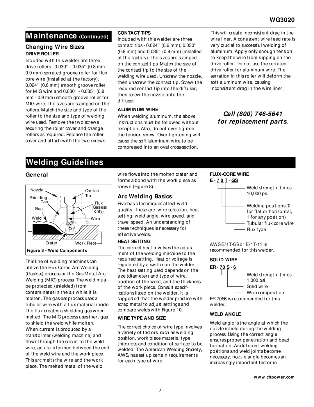
Nozzle | Contact | |
Shielding | Tip | |
| ||
Gas | Flux | |
Slag | (Gasless | |
only) | ||
| ||
Weld | Wire | |
Crater | Work Piece | |
Figure 8 - Weld Components | ||
This line of welding machines can utilize the Flux Cored Arc Welding (Gasless) process or the Gas Metal Arc Welding (MIG) process. The weld must be protected (shielded) from contaminates in the air while it is molten. The gasless process uses a tubular wire with a flux material inside. The flux creates a shielding gas when melted. The MIG process uses inert gas to shield the weld while molten.
When current is produced by a transformer (welding machine) and flows through the circuit to the weld wire, an arc is formed between the end of the weld wire and the work piece. This arc melts the wire and the work piece. The melted metal of the weld
wire flows into the molten crater and forms a bond with the work piece as shown (Figure 8).
Arc Welding Basics
Five basic techniques affect weld quality. These are: wire selection, heat setting, weld angle, wire speed, and travel speed. An understanding of these techniques is necessary for effective welds.
HEAT SETTING
The correct heat involves the adjust- ment of the welding machine to the required setting. Heat or voltage is regulated by a switch on the welder. The heat setting used depends on the size (diameter) and type of wire, position of the weld, and the thickness of the work piece. Consult specif- ications listed on the welder. It is suggested that the welder practice with scrap metal to adjust settings and compare welds with Figure 10.
WIRE TYPE AND SIZE
The correct choice of wire type involves a variety of factors, such as welding position, work piece material type, thickness and condition of surface to be welded. The American Welding Society, AWS, has set up certain requirements for each type of wire.
FLUX-CORE WIRE
E - 7 0 T - GS
Weld strength, times 10,000 psi
Welding positions (0 for flat or horizontal, 1 for any position)
Tubular flux core wire Flux type
AWS
SOLID WIRE
ER - 70 S - 6
Weld strength, times
1,000 psi Solid wire
Wire composition
WELD ANGLE
Weld angle is the angle at which the nozzle is held during the welding process. Using the correct angle ensures proper penetration and bead formation. As different welding positions and weld joints become necessary, nozzle angle becomes an increasingly important factor in
www.chpower.com
7