The control module also monitors the high-pressure switch(es) and compressor internal thermal protection (30HW). If at any time one or both of these switches opens, the con- trol module shuts down the compressor and places the unit in a lockout condition. The control module activates the fault indication circuit, and the unit service lamp is illuminated. The unit cannot be restarted until control power is manually cycled to OFF, then to ON.

If the unit shuts down on an automatic reset switch, such as the temperature controller, the compressor will be al- lowed to restart when the switch closes and the control mod- ule anti-short-cycle time has elapsed.

For Servicing Only Ð To speed up the 5-minute anti-short cycle, a jumper may be placed between terminals T1 and T6 of the control module.

This jumper must be removed after servicing is complete. Failure to remove this jumper is considered abusive treat- ment and will void the Carrier warranty.

HIGH-PRESSURE SWITCH Ð A high-pressure switch is provided to protect each compressor and refrigeration sys- tem from unsafe high pressure conditions. See Table 8 for high-pressure switch settings.

The high-pressure switch is mounted in the discharge side of each compressor. A snubber is provided between the com- pressor discharge manifold and the high-pressure switch to prevent pressure pulsations from damaging the switch.

If an unsafe, high-pressure condition should exist, the switch opens and shuts off the affected compressor. The unit control module prevents the unit from restarting. The unit will not restart until control power is manually cycled off, then on.

To check operation of the switch, slowly close the com- pressor discharge shutoff valve until the compressor shuts down. The switch should open at the pressure corresponding to the appropriate switch setting as shown in Table 8.

Table 8 Ð Factory Settings, High-Pressure Switch

(Fixed)

UNIT

CUTOUT

CUT-IN

30

Psig

kPa

Psig

kPa

HK, HWS

280 ± 10

1931 ± 69

180 ± 20

1241 ± 138

HL, HWB, HWC

375 ± 10

2585 ± 69

275 ± 20

1896 ± 138

HWA

395 ± 10

2723 ± 69

298 ± 20

2054 ± 138


Reopen the compressor discharge shutoff valve, and cycle the unit ON-OFF switch to OFF, then ON. The unit should restart after the compressor anti-short-cycle delay, built into the unit control module, expires.

LOW-PRESSURE SWITCH Ð A low-pressure switch is pro- vided to protect each compressor and system from a loss of refrigerant. The low-pressure switch(es) also provides freeze protection for the cooler. The low-pressure switch(es) is non- adjustable. See Table 9 for low-pressure switch settings. One switch is used for standard units, and a different switch is used for units with the brine option.

Table 9 Ð Factory Settings, Low-Pressure Switch

(Fixed)

UNIT

CUTOUT


CUT-IN

TYPE

Psig

kPa

Psig


kPa

STANDARD

42 ± 3

290 ± 21

57 ± 5


393 ± 34

BRINE

27 ± 3

186 ± 21

44 ± 5


303 ± 34


To check operation of the low-pressure switch, slowly close the suction service valve and allow the affected compressor to pump down. The compressor should cut out when the suc- tion pressure falls below the low-pressure switch cutout set- ting. Open the suction service valve. The compressor should restart after the low-pressure switch closes, and the com- pressor anti-short-cycle delay expires.

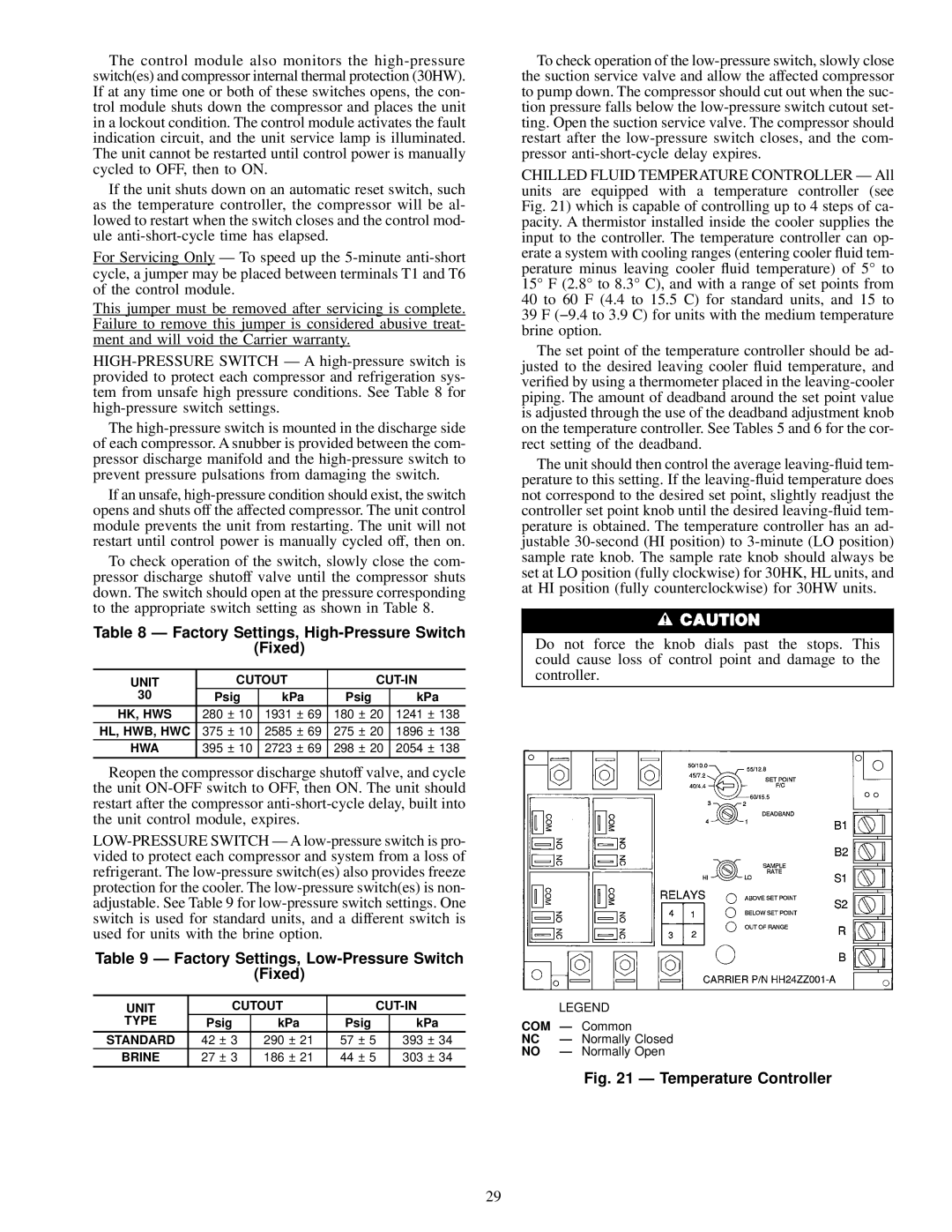
CHILLED FLUID TEMPERATURE CONTROLLER Ð All units are equipped with a temperature controller (see Fig. 21) which is capable of controlling up to 4 steps of ca- pacity. A thermistor installed inside the cooler supplies the input to the controller. The temperature controller can op- erate a system with cooling ranges (entering cooler ¯uid tem- perature minus leaving cooler ¯uid temperature) of 5° to 15° F (2.8° to 8.3° C), and with a range of set points from 40 to 60 F (4.4 to 15.5 C) for standard units, and 15 to 39 F (−9.4 to 3.9 C) for units with the medium temperature brine option.

The set point of the temperature controller should be ad- justed to the desired leaving cooler ¯uid temperature, and veri®ed by using a thermometer placed in the leaving-cooler piping. The amount of deadband around the set point value is adjusted through the use of the deadband adjustment knob on the temperature controller. See Tables 5 and 6 for the cor- rect setting of the deadband.

The unit should then control the average leaving-¯uid tem- perature to this setting. If the leaving-¯uid temperature does not correspond to the desired set point, slightly readjust the controller set point knob until the desired leaving-¯uid tem- perature is obtained. The temperature controller has an ad- justable 30-second (HI position) to 3-minute (LO position) sample rate knob. The sample rate knob should always be set at LO position (fully clockwise) for 30HK, HL units, and at HI position (fully counterclockwise) for 30HW units.

Do not force the knob dials past the stops. This could cause loss of control point and damage to the controller.


LEGEND

COM Ð Common

NC

Ð Normally Closed

NO

Ð Normally Open

Fig. 21 Ð Temperature Controller

29

Page 29
Image 29
Carrier 30HL050, 30HW018-040, 060 Factory Settings, High-Pressure Switch Fixed, Factory Settings, Low-Pressure Switch Fixed

30HK040-060, 060, 30HL050, 30HW018-040 specifications

The Carrier 30HW018-040, 30HL050, 060, and 30HK040-060 series represents a range of advanced rooftop units designed to meet the diverse heating and cooling needs of commercial buildings. Renowned for their efficiency and performance, these units incorporate cutting-edge technologies to improve operational effectiveness and reduce energy consumption.

One of the standout features of the Carrier 30HW series is its high-efficiency scroll compressors, which are engineered to provide exceptional cooling capacity while minimizing energy usage. These compressors operate quietly and ensure smooth performance across varying loads. Additionally, the units utilize advanced microprocessor controls that enhance system efficiency by enabling precise temperature regulation and optimizing energy consumption based on real-time weather conditions.

Another important aspect of the 30HL series is its ability to provide reliable heating and cooling capabilities even in extreme weather conditions. With robust heat exchangers and a range of variable-speed fans, these units can efficiently circulate air while maintaining optimal indoor comfort levels. Variable-speed technology not only enhances comfort but also improves energy savings, as the system can adjust its output based on occupancy and external temperature fluctuations.

The 30HK series, specifically designed for high-performance applications, features enhanced filtration systems which improve indoor air quality. These systems are capable of accommodating various filter types, ensuring that airborne contaminants are effectively captured. This makes the 30HK a suitable choice for environments where air quality is a priority, such as schools, hospitals, and commercial offices.

Moreover, all units in the 30HW, 30HL, and 30HK series are designed with ease of maintenance in mind. Removable panels and easy access points allow for quick servicing and reduces downtime. The compact design also ensures that installation is straightforward, making them a preferred choice for many contractors.

In summary, Carrier's 30HW018-040, 30HL050, 060, and 30HK040-060 series are integral solutions in the HVAC market, combining energy efficiency, advanced controls, and superior air quality features. These rooftop units are tailored for commercial applications, providing reliable heating and cooling solutions while prioritizing comfort and sustainability. Through continuous innovation, Carrier remains at the forefront of HVAC technology, ensuring that their products meet the evolving demands of the industry.