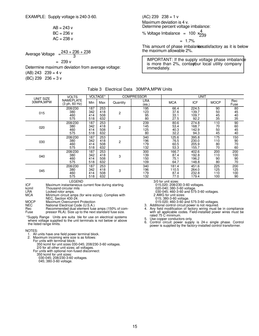
30MPA specifications
The Carrier 30MPA is a prominent industrial chiller unit known for its outstanding performance and efficiency in cooling applications. Designed for mid-sized commercial and industrial facilities, it exemplifies cutting-edge technology and engineering.One of the main features of the Carrier 30MPA is its advanced scroll compressor technology. This innovative design allows for improved efficiency and reduced energy consumption compared to traditional chiller units. The compressors are known for their reliability and quiet operation, making the 30MPA ideal for environments where noise is a concern.
The unit employs a high-efficiency economizer mode, which optimizes energy use during cooler ambient conditions. By utilizing outside air for cooling, the economizer significantly reduces the chiller's energy demand, promoting sustainability and cost savings.
Additionally, the 30MPA is equipped with a microprocessor-based control system. This intelligent control technology allows for precise monitoring and adjustment of system performance, enhancing both comfort and efficiency. The controls come with various customizable settings, enabling users to tailor the chiller's operation to meet specific needs.
The 30MPA also stands out with its robust construction and design. It features a compact footprint, allowing for easy installation in confined spaces. Its weather-resistant casing and corrosion-resistant components ensure durability and long service life, even in harsh environments.
Moreover, the Carrier 30MPA incorporates an environmentally friendly refrigerant, which complies with global regulations aimed at reducing ozone depletion and greenhouse gas emissions. This commitment to environmental responsibility aligns with Carrier's goal of promoting sustainable building practices.
Another important characteristic is its flexible configuration options. The unit can accommodate different system designs and requirements, making it suitable for a wide range of applications, from chilled water systems in hospitals to comfort cooling in office buildings.
In summary, the Carrier 30MPA chiller combines innovative technology, energy efficiency, and robust design, making it a standout choice for commercial and industrial cooling applications. Its advanced features and sustainable approach not only ensure reliable performance but also contribute to lower operational costs and reduced environmental impact.

