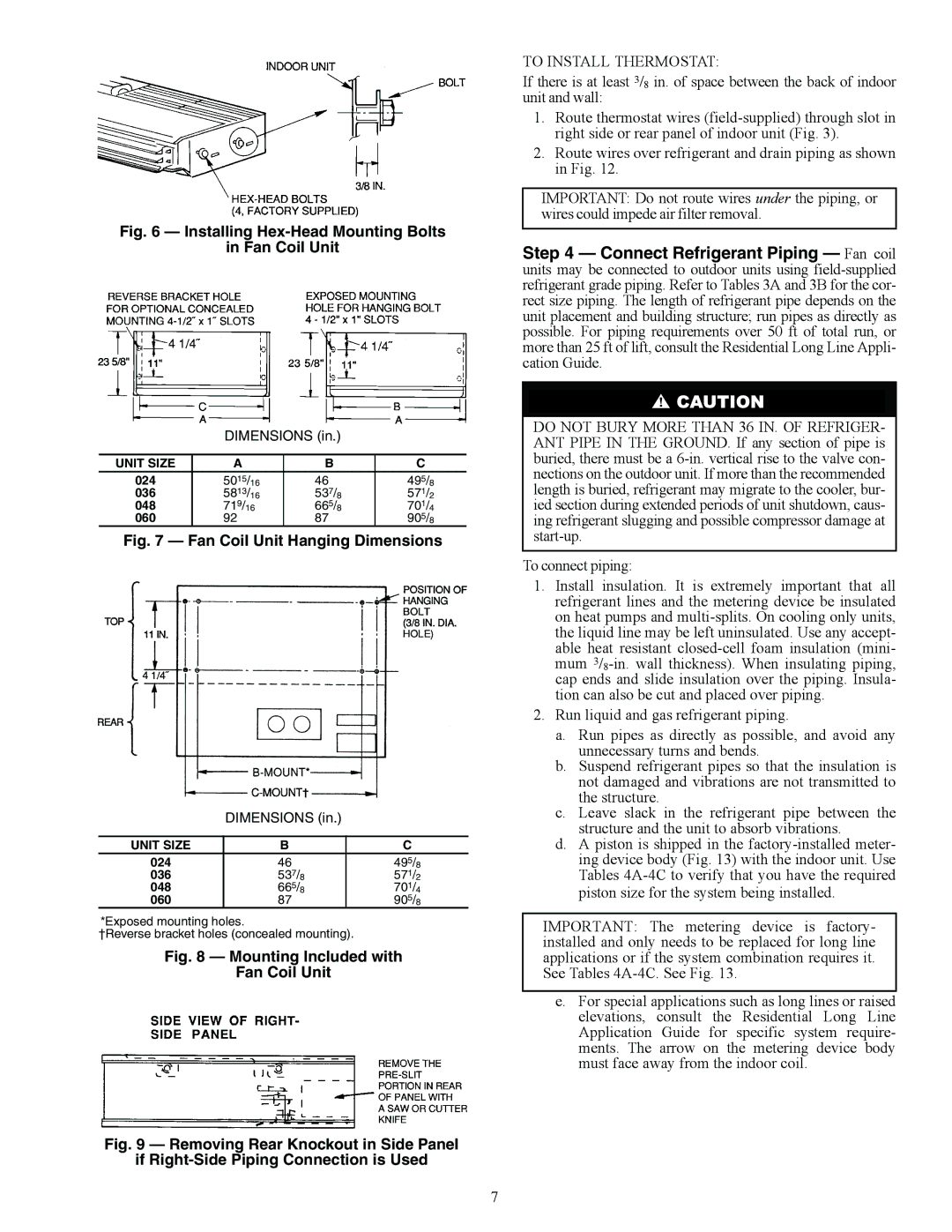
Fig. 6 — Installing Hex-Head Mounting Bolts

in Fan Coil Unit

DIMENSIONS (in.)

UNIT SIZE

A

B

C

024

5015/16

46

495/8

036

5813/16

537/8

571/2

048

719/16

665/8

701/4

060

92

87

905/8

Fig. 7 — Fan Coil Unit Hanging Dimensions

DIMENSIONS (in.)

UNIT SIZE

B

C

024

46

495/8

036

537/8

571/2

048

665/8

701/4

060

87

905/8

*Exposed mounting holes.

†Reverse bracket holes (concealed mounting).

Fig. 8 — Mounting Included with

Fan Coil Unit

Fig. 9 — Removing Rear Knockout in Side Panel

if Right-Side Piping Connection is Used

TO INSTALL THERMOSTAT:

If there is at least 3/8 in. of space between the back of indoor unit and wall:

1.Route thermostat wires (field-supplied) through slot in right side or rear panel of indoor unit (Fig. 3).

2.Route wires over refrigerant and drain piping as shown in Fig. 12.

IMPORTANT: Do not route wires under the piping, or wires could impede air filter removal.

Step 4 — Connect Refrigerant Piping — Fan coil units may be connected to outdoor units using field-supplied refrigerant grade piping. Refer to Tables 3A and 3B for the cor- rect size piping. The length of refrigerant pipe depends on the unit placement and building structure; run pipes as directly as possible. For piping requirements over 50 ft of total run, or more than 25 ft of lift, consult the Residential Long Line Appli- cation Guide.

DO NOT BURY MORE THAN 36 IN. OF REFRIGER- ANT PIPE IN THE GROUND. If any section of pipe is buried, there must be a 6-in. vertical rise to the valve con- nections on the outdoor unit. If more than the recommended length is buried, refrigerant may migrate to the cooler, bur- ied section during extended periods of unit shutdown, caus- ing refrigerant slugging and possible compressor damage at start-up.

To connect piping:

1.Install insulation. It is extremely important that all refrigerant lines and the metering device be insulated on heat pumps and multi-splits. On cooling only units, the liquid line may be left uninsulated. Use any accept- able heat resistant closed-cell foam insulation (mini- mum 3/8-in. wall thickness). When insulating piping, cap ends and slide insulation over the piping. Insula- tion can also be cut and placed over piping.

2.Run liquid and gas refrigerant piping.

a.Run pipes as directly as possible, and avoid any unnecessary turns and bends.

b.Suspend refrigerant pipes so that the insulation is not damaged and vibrations are not transmitted to the structure.

c.Leave slack in the refrigerant pipe between the structure and the unit to absorb vibrations.

d.A piston is shipped in the factory-installed meter- ing device body (Fig. 13) with the indoor unit. Use Tables 4A-4C to verify that you have the required piston size for the system being installed.

IMPORTANT: The metering device is factory- installed and only needs to be replaced for long line applications or if the system combination requires it. See Tables 4A-4C. See Fig. 13.

e.For special applications such as long lines or raised elevations, consult the Residential Long Line Application Guide for specific system require- ments. The arrow on the metering device body must face away from the indoor coil.

7

Page 7
Image 7
Carrier 40QA024-060 specifications Installing Hex-Head Mounting Bolts Fan Coil Unit

40QA024-060 specifications

The Carrier 40QA024-060 represents a significant advancement in the field of air conditioning and heat pump systems, designed to provide efficient climate control for both residential and commercial applications. This package unit integrates cutting-edge technologies to enhance performance, reliability, and ease of use, making it an ideal choice for a variety of settings.

One of the standout features of the 40QA024-060 is its energy efficiency. The unit is equipped with a high-efficiency compressor that is designed to minimize power consumption while still delivering optimal cooling and heating performance. This translates into lower energy bills and a reduced environmental footprint, aligning with the growing demand for sustainability in HVAC systems.

Another important characteristic of the Carrier 40QA024-060 is its compact design. The unit is engineered for space-saving installations, making it suitable for locations where space is at a premium. Its durable construction ensures longevity and reliability in various weather conditions, providing peace of mind for users.

The 40QA024-060 utilizes advanced refrigerant technologies, including the use of R-410A refrigerant, which is known for its superior cooling capabilities and lower ozone depletion potential compared to older refrigerants. This aligns with modern environmental standards and contributes to the goal of eco-friendly operation.

In terms of operation, the unit features a microprocessor-based control system that allows for precise temperature management. Users can easily set their desired indoor climate settings, and the system will automatically adjust operational parameters to maintain those conditions efficiently.

Flexibility is also a key advantage of the Carrier 40QA024-060. The unit offers various configurations and can be integrated with existing ductwork, making it adaptable to different residential or commercial layouts. Additionally, the option for variable-speed blower technology enhances comfort by providing consistent airflow and reducing temperature fluctuations.

The Carrier 40QA024-060 is also designed with serviceability in mind. Access panels and maintenance features make it easy for technicians to perform routine inspections or repairs, reducing downtime and ensuring optimal performance over the unit's lifespan.

In conclusion, the Carrier 40QA024-060 combines energy efficiency, advanced technology, and robust design to meet the demands of climate control in diverse environments. Its features make it a reliable choice for both residential and commercial applications, contributing to enhanced comfort and operational efficiency.