EPM Chip — The drive uses a electronic programming module (EPM) chip to store the program parameters. This is an EEPROM memory chip and is accessible from the front of the VFD. It should not be removed with power applied to the VFD.

Loss of CCN Communications — Carrier Comfort Network® (CCN) communications with external control systems can be affected by high frequency electrical noise

generated by the Motormaster® V control. Ensure unit is well grounded to eliminate ground currents along communication lines.

If communications are lost only while Motormaster V con- trol is in operation, order a signal isolator (CEAS420876-2) and power supplies (CEAS221045-01, 2 required) for the CCN communication line.

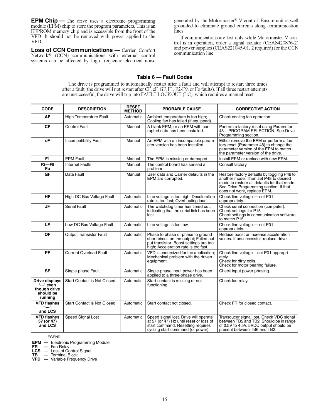
Table 6 — Fault Codes

The drive is programmed to automatically restart after a fault and will attempt to restart three times after a fault (the drive will not restart after CF, cF, GF, F1, F2-F9, or Fo faults). If all three restart attempts are unsuccessful, the drive will trip into FAULT LOCKOUT (LC), which requires a manual reset.


CODE

DESCRIPTION

RESET

PROBABLE CAUSE

CORRECTIVE ACTION


METHOD


AF

High Temperature Fault

Automatic

Ambient temperature is too high;

Check cooling fan operation.


Cooling fan has failed (if equipped).


CF

Control Fault

Manual

A blank EPM, or an EPM with cor-

Perform a factory reset using Parameter


rupted data has been installed.

48 – PROGRAM SELECTION. See Drive


Programming section.


cF

Incompatibility Fault

Manual

An EPM with an incompatible param-

Either remove the EPM or perform a fac-


eter version has been installed.

tory reset (Parameter 48) to change the


parameter version of the EPM to match


the parameter version of the drive.


F1

EPM Fault

Manual

The EPM is missing or damaged.

Install EPM or replace with new EPM.


F2—F9

Internal Faults

Manual

The control board has sensed a

Consult factory.


Fo


problem


GF

Data Fault

Manual

User data and Carrier defaults in the

Restore factory defaults by toggling P48 to


EPM are corrupted.

another mode. Then set P48 to desired


mode to restore all defaults for that mode.


See Drive Programming section. If that


does not work, replace EPM.


HF

High DC Bus Voltage Fault

Automatic

Line voltage is too high; Deceleration

Check line voltage — set P01


rate is too fast; Overhauling load.

appropriately.


JF

Serial Fault

Automatic

The watchdog timer has timed out,

Check serial connection (computer).


indicating that the serial link has been

Check settings for P15.


lost.

Check settings in communication software


to match P15.


LF

Low DC Bus Voltage Fault

Automatic

Line voltage is too low.

Check line voltage — set P01


appropriately.


OF

Output Transistor Fault

Automatic

Phase to phase or phase to ground

Reduce boost or increase acceleration


short circuit on the output; Failed out-

values. If unsuccessful, replace drive.


put transistor; Boost settings are too


high; Acceleration rate is too fast.


PF

Current Overload Fault

Automatic

VFD is undersized for the application;

Check line voltage – set P01 appropri-


Mechanical problem with the driven

ately.


equipment.

Check for dirty coils.


Check for motor bearing failure.


SF

Single-phase Fault

Automatic

Single-phase input power has been

Check input power phasing.


applied to a three-phase drive.


Drive displays

Start Contact is Not Closed

Automatic

Start contact is missing or not

Check fan relay.

‘---’ even


functioning.


though drive


should be


running


VFD flashes

Start Contact is Not Closed

Automatic

Start contact not closed.

Check FR for closed contact.


“---”


and LCS


VFD flashes

Speed Signal Lost

Automatic

Speed signal lost. Drive will operate

Transducer signal lost. Check VDC signal

57 (or 47)


at 57 (or 47) Hz until reset or loss of

between TB5 and TB2. Should be in range

and LCS


start command. Resetting requires

of 0.5V to 4.5V. 5VDC output should be


cycling start command (or power).

present between TB6 and TB2.


LEGEND


EPM — Electronic Programming Module


FR

Fan Relay


LCS

Loss of Control Signal


TB

Terminal Block


VFD — Variable Frequency Drive

15

Page 15
Image 15
Carrier 48/50P5030-100, 48/50P4, 48/50P2, 48/50P3 installation instructions Fault Codes, F2-F9

48/50P5030-100, 48/50P3, 48/50P2, 48/50P4 specifications

The Carrier 48/50P5030-100, 48/50P4, 48/50P3, and 48/50P2 series represent a range of highly efficient air conditioning and heating solutions developed by Carrier. Designed for commercial and industrial applications, these units combine advanced technology with robust features to deliver reliable performance and comfort.

One of the standout features of the Carrier 48/50P series is their energy efficiency. These units are equipped with high-efficiency compressors and fans that optimize energy use while maintaining superior cooling and heating capabilities. The models often meet or exceed ASHRAE efficiency standards, providing significant energy savings over traditional systems. This makes them not only cost-effective over their lifespan but also a responsible choice for energy-conscious businesses.

The 48/50P5030-100 model is notable for its ability to deliver precise temperature control, thanks to its sophisticated microprocessor control panel. This control system allows for easy adjustments and provides valuable diagnostic information, ensuring operational reliability and maintenance efficiency. The advanced controls also support variable-speed technology, which adjusts the system’s output based on real-time demands, enhancing both comfort and energy savings.

In terms of construction, these units are designed for durability. With a rugged, weather-resistant cabinet and high-quality components, they can withstand harsh environmental conditions, making them suitable for a variety of settings. The units typically include high-efficiency filters that improve indoor air quality by reducing airborne particles and allergens.

Another key characteristic of the Carrier 48/50P series is their versatility. These units can be configured for various applications, including rooftop installations and ground-mounted setups. Their modular design allows for easy integration into existing systems, accommodating different space requirements while providing optimal performance.

Carrier also emphasizes noise reduction in the design of these units, incorporating sound-dampening technologies that minimize operational noise. This is particularly valuable in environments where quiet operation is essential, such as schools and offices.

Overall, the Carrier 48/50P5030-100, 48/50P4, 48/50P3, and 48/50P2 series represent a commitment to quality, efficiency, and innovation in climate control solutions. With their advanced features, energy-saving technologies, and robust design, these models are well-suited to meet the diverse needs of modern commercial and industrial facilities. Carrier continues to lead the industry by integrating cutting-edge technology with a focus on performance and sustainability, ensuring that their systems provide long-term comfort and efficiency.