completes the control circuit. The
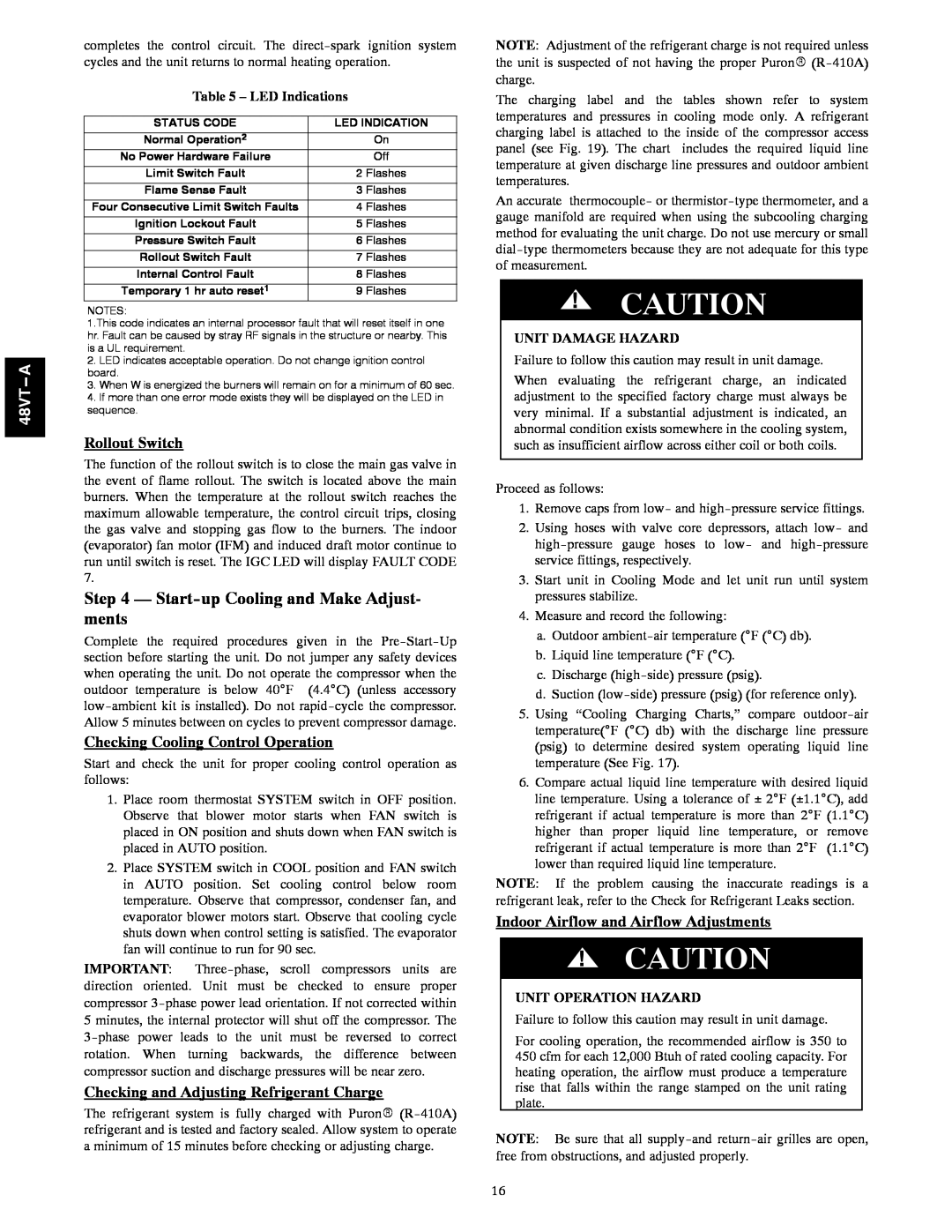
Table 5 – LED Indications
STATUS CODE | LED INDICATION |
Normal Operation2 | On |
No Power Hardware Failure | Off |
Limit Switch Fault | 2 Flashes |
Flame Sense Fault | 3 Flashes |
Four Consecutive Limit Switch Faults | 4 Flashes |
Ignition Lockout Fault | 5 Flashes |
Pressure Switch Fault | 6 Flashes |
Rollout Switch Fault | 7 Flashes |
Internal Control Fault | 8 Flashes |
Temporary 1 hr auto reset1 | 9 Flashes |
NOTES:
1.This code indicates an internal processor fault that will reset itself in one hr. Fault can be caused by stray RF signals in the structure or nearby. This is a UL requirement.
2.LED indicates acceptable operation. Do not change ignition control board.
3.When W is energized the burners will remain on for a minimum of 60 sec.
4.If more than one error mode exists they will be displayed on the LED in sequence.
Rollout Switch
The function of the rollout switch is to close the main gas valve in the event of flame rollout. The switch is located above the main burners. When the temperature at the rollout switch reaches the maximum allowable temperature, the control circuit trips, closing the gas valve and stopping gas flow to the burners. The indoor (evaporator) fan motor (IFM) and induced draft motor continue to run until switch is reset. The IGC LED will display FAULT CODE 7.
Step 4 — Start-up Cooling and Make Adjust- ments
Complete the required procedures given in the
Checking Cooling Control Operation
Start and check the unit for proper cooling control operation as follows:
1.Place room thermostat SYSTEM switch in OFF position. Observe that blower motor starts when FAN switch is placed in ON position and shuts down when FAN switch is placed in AUTO position.
2.Place SYSTEM switch in COOL position and FAN switch in AUTO position. Set cooling control below room temperature. Observe that compressor, condenser fan, and evaporator blower motors start. Observe that cooling cycle shuts down when control setting is satisfied. The evaporator fan will continue to run for 90 sec.
IMPORTANT:
Checking and Adjusting Refrigerant Charge
The refrigerant system is fully charged with PuronR
NOTE: Adjustment of the refrigerant charge is not required unless the unit is suspected of not having the proper PuronR
The charging label and the tables shown refer to system temperatures and pressures in cooling mode only. A refrigerant charging label is attached to the inside of the compressor access panel (see Fig. 19). The chart includes the required liquid line temperature at given discharge line pressures and outdoor ambient temperatures.
An accurate thermocouple- or
!CAUTION
UNIT DAMAGE HAZARD
Failure to follow this caution may result in unit damage.
When evaluating the refrigerant charge, an indicated adjustment to the specified factory charge must always be very minimal. If a substantial adjustment is indicated, an abnormal condition exists somewhere in the cooling system, such as insufficient airflow across either coil or both coils.
Proceed as follows:
1.Remove caps from low- and
2.Using hoses with valve core depressors, attach low- and
3.Start unit in Cooling Mode and let unit run until system pressures stabilize.
4.Measure and record the following:
a.Outdoor
b.Liquid line temperature (°F (°C).
c.Discharge
d.Suction
5.Using “Cooling Charging Charts,” compare
6.Compare actual liquid line temperature with desired liquid line temperature. Using a tolerance of ± 2°F (±1.1°C), add refrigerant if actual temperature is more than 2°F (1.1°C) higher than proper liquid line temperature, or remove refrigerant if actual temperature is more than 2°F (1.1°C) lower than required liquid line temperature.
NOTE: If the problem causing the inaccurate readings is a refrigerant leak, refer to the Check for Refrigerant Leaks section.
Indoor Airflow and Airflow Adjustments
!CAUTION
UNIT OPERATION HAZARD
Failure to follow this caution may result in unit damage.
For cooling operation, the recommended airflow is 350 to 450 cfm for each 12,000 Btuh of rated cooling capacity. For heating operation, the airflow must produce a temperature rise that falls within the range stamped on the unit rating plate.
NOTE: Be sure that all
16