Table 1 – Physical Data - Unit 48VT-A
|
|
|
|
|
|
|
|
|
|
|
|
| ||||||||||
UNIT SIZE |
|
| 024040 | 024060 | 030040 |
| 030060 | 036060 | 036090 | 042060 |
| 042090 | ||||||||||
NOMINAL CAPACITY | ton |
|
| 2 |
| 2 | 1/2 |
| 1/2 |
| 3 |
| 3 | 1/2 |
| 1/2 | ||||||
SHIPPING WEIGHT | lb. |
| 368 | 368 | 378 |
| 378 | 450 | 450 | 491 |
| 491 | ||||||||||
|
|
| (kg) |
| 167 | 167 | 171 |
| 171 | 204 | 204 | 223 |
| 223 | ||||||||
COMPRESSORS |
|
|
|
|
|
|
|
|
|
| Scroll |
|
|
|
|
|
|
|
| |||
Quantity |
|
|
|
|
|
|
|
|
|
| 1 |
|
|
|
|
|
|
|
|
| ||
REFRIGERANT (R |
| 9.5 | 9.5 | 10.5 |
| 10.5 | 9.0 | 9.0 | 14.0 |
| 14.0 | |||||||||||
Quantity | lb |
|
|
|
| |||||||||||||||||
|
| (kg) |
|
| 4.3 | 4.3 | 4.8 |
| 4.8 | 4.1 | 4.1 | 6.4 |
| 6.4 | ||||||||
REFRIGERANT METERING |
|
|
|
|
|
|
| Indoor TXV, Outdoor Accurater |
|
|
|
|
|
|
| |||||||
DEVICE |
|
|
|
|
|
|
|
|
|
|
|
|
|
|
| |||||||
|
|
|
|
|
|
|
|
|
|
|
|
|
|
|
|
|
|
|
| |||
OUTDOOR ORIFICE |
|
|
|
|
|
|
|
|
|
|
|
|
|
| 0.038 (Left OD Coil) | |||||||
in. (qty) |
|
| 0.032 (2) | 0.032 (2) | 0.038 (2) |
| 0.038 (2) | 0.040 (2) | 0.040 (2) | |||||||||||||
|
|
| 0.040 (Right OD Coil) | |||||||||||||||||||
(mm) |
|
|
| .81 | .81 | .97 |
| .97 | 1.02 | 1.02 |
| .97/1.02 |
|
| ||||||||
OUTDOOR COIL |
|
| 2 | ...21 | 2 | ...21 | 2... | 21 |
| 2... | 21 | 2 | ...21 | 2 | ...21 | 2... | 21 |
| 2... | 21 | ||
Rows...Fins/in. |
|
|
|
| ||||||||||||||||||
Face | sq ft |
|
| 13.6 | 13.6 | 15.4 |
| 15.4 | 13.6 | 13.6 | 19.4 |
| 19.4 | |||||||||
OUTDOOR FAN |
|
|
|
|
|
|
|
|
|
|
|
|
|
|
|
|
|
|
|
| ||
Nominal Cfm |
|
| 2500 | 2500 | 2600 |
| 2600 | 3000 | 3000 | 3500 |
| 3500 | ||||||||||
in. |
|
|
| 22 |
| 22 |
| 22 |
|
| 22 |
| 22 |
| 22 |
| 22 |
|
| 22 | ||
|
| (mm) |
| 559 | 559 | 559 |
| 559 | 559 | 559 | 559 |
| 559 | |||||||||
Motor Hp (Rpm) |
|
| 1/8 (825) | 1/8 (825) | 1/8 (825) |
| 1/8 (825) | 1/4 (1100) | 1/4 (1100) | 1/8 (825) |
| 1/8 (825) | ||||||||||
INDOOR COIL |
|
| 3... | 17 | 3... | 17 | 3... | 17 |
| 3... | 17 | 3... | 17 | 3... | 17 | 3... | 17 |
| 3... | 17 | ||
Rows...Fins/in. |
|
|
|
| ||||||||||||||||||
Face | sq ft |
|
| 3.7 | 3.7 | 3.7 |
| 3.7 | 4.7 | 4.7 | 4.7 |
| 4.7 | |||||||||
INDOOR BLOWER |
|
|
|
|
|
|
|
|
|
|
|
|
|
|
|
|
|
|
|
| ||
Nominal Cooling | (CFM) |
| 800 | 800 | 1000 |
| 1000 | 1200 | 1200 | 1400 |
| 1400 | ||||||||||
in. |
|
| 10x10 | 10x10 | 10x10 |
| 10x10 | 11x10 | 11x10 | 11x10 |
| 11x10 | ||||||||||
| (mm) |
|
| 254x254 | 254x254 | 254x254 |
| 254x254 | 279x254 | 279x254 | 279x254 |
| 279x254 | |||||||||
Motor |
|
| 1/2 | 1/2 | 1/2 |
| 1/2 | 3/4 | 3/4 | 3/4 |
| 3/4 | ||||||||||
FURNACE SECTION* |
|
|
|
|
|
|
|
|
|
|
|
|
|
|
|
|
|
|
| |||
Burner Orifice |
|
| 2 | ...44 | 2 | ...38 | 2... | 44 |
| 2... | 44 | 2 | ...38 | 3 | ...38 | 2... | 38 |
| 3... | 38 | ||
Natural Gas Qty... | Drill Size |
|
|
| ||||||||||||||||||
Propane GasQty... | Drill Size |
| 2 | ...55 | 2 | ...53 | 2... | 55 |
| 2... | 53 | 2 | ...53 | 3 | ...53 | 2... | 53 |
| 3... | 53 | ||
|
|
|
|
|
|
|
|
| 650 +/ |
|
|
|
|
|
|
|
| |||||
(psig) | out |
|
|
|
|
|
|
|
|
|
|
|
|
|
|
|
|
|
| |||
Reset (Auto) |
|
|
|
|
|
|
|
|
|
| 420 +/ |
|
|
|
|
|
|
|
| |||
CHARGE / |
|
|
|
|
|
|
|
|
|
|
|
|
|
|
|
|
|
|
| |||
|
|
|
|
|
|
|
|
|
|
|
|
|
|
|
|
|
|
| ||||
(Liquid Line) (psig) |
|
|
|
|
|
|
|
|
|
|
|
|
|
|
|
|
|
|
|
| ||
out |
|
|
|
|
|
|
|
|
|
| 20 +/ |
|
|
|
|
|
|
|
| |||
Reset (auto) |
|
|
|
|
|
|
|
|
|
| 45 | 10 |
|
|
|
|
|
|
|
| ||
| 20x20x1 |
|
| 20x24x1 |
|
|
|
|
|
| 24x30x1 |
|
|
|
| |||||||
Throwaway | (in.) |
|
|
|
|
|
|
|
|
|
|
|
|
|
| |||||||
|
| (mm) |
|
| 508x508x25 |
|
| 508x610x25 |
|
|
|
| 610x762x25 |
|
|
|
| |||||
*Based on altitude of 0 to 2000 ft | 610 m). |
|
|
|
|
|
|
|
|
|
|
|
|
|
|
|
|
| ||||
{Required filter sizes shown are based on the larger of the ARI (Air Conditioning and Refrigeration Institute) rated cooling airflow or the heating airflow velocity of 300 ft/minute for high
}If using accessory filter rack refer to filter rack installation instructions for correct filter size and quantity.
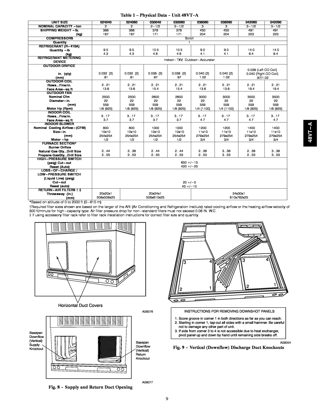
Basepan Downflow (Vertical) Supply Knockout
Horizontal Duct Covers
A09076
Basepan Downflow (Vertical) Return Knockout
A09077
Fig. 8 - Supply and Return Duct Opening
3 | 4 | 3 |
| 4 |
|
| |||
2 | 1 |
| 2 | 1 |
|
| |||
|
|
| ||
|
|
|
|
INSTRUCTIONS FOR REMOVING DOWNSHOT PANELS
1.Score groove in corner 1 in both directions as far as you can reach.
2.Starting in corner 1,
3.If side from corner 3 to 4 is not accessible due to heat exchanger, pivot panel up and down by hand until remaining side breaks off.
A09054
Fig. 9 - Vertical (Downflow) Discharge Duct Knockouts
9