Manuals
/
Carrier
/
Household Appliance
/
Air Conditioner
Carrier
48VT(N)
installation instructions
208/230-3-60Wiring Diagram, Unit 48VT-A, 48VT--A, A09209
Models:
48VT(N)
1
25
38
38
Download
38 pages
51.43 Kb
22
23
24
25
26
27
28
29
Troubleshooting
Install
Electrical Controls and Wiring
Dimension
Maintenance
Symptom
Unit Access Panels
Burner Assembly
Checklist
Limit Switches
Page 25
Image 25
48VT--
A
A09209
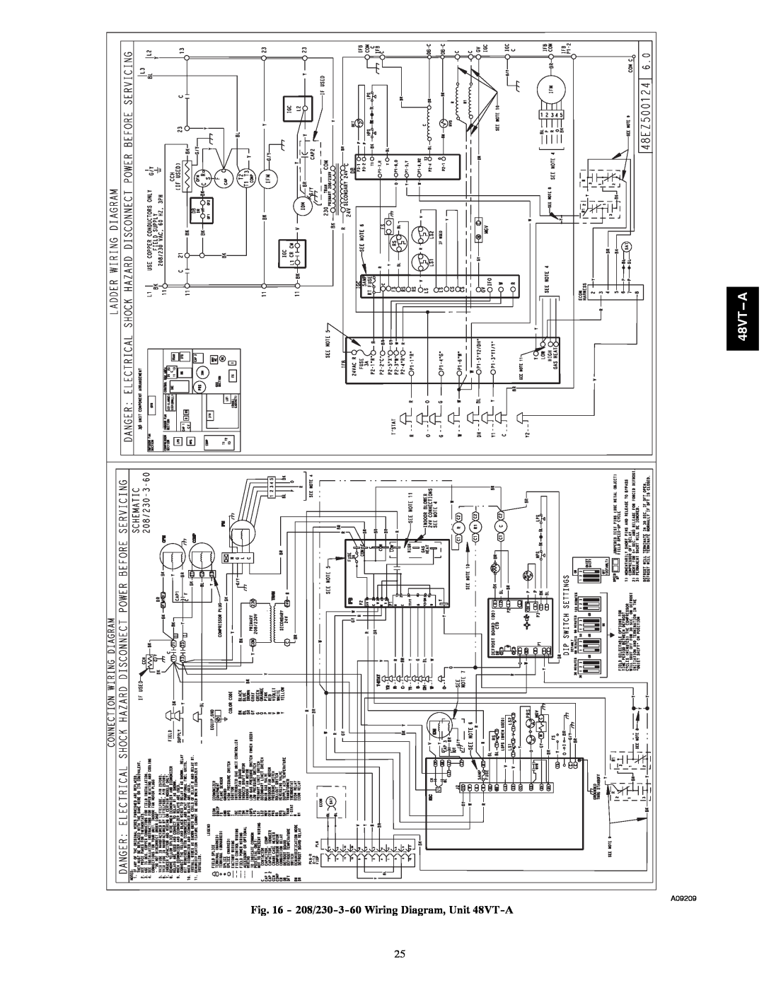
Fig. 16 -
208/230-3-60
Wiring Diagram, Unit
48VT-A
25
Page 24
Page 26
Page 25
Image 25
Page 24
Page 26
Contents
SAFETY CONSIDERATIONS
TABLE OF CONTENTS
Fig. 1 - Unit 48VT-A
Installation Instructions
INTRODUCTION
RECEIVING AND INSTALLATION
Step 1 - Check Equipment
Step 2 - Provide Unit Support
48VT--A
Fig. 2 - 48VT-A24-30Unit Dimensions
A09146
48VT--A
Fig. 3 - 48VT-A36-60Unit Dimensions
A09147
48VT
Fig. 4 - Roof Curb Dimensions
SMALL CURB
ROOF CURB DETAIL
Step 5 - Rig and Place Unit
ACCESS PANELS MUST BE IN PLACE WHEN RIGGING
Inspection
Rigging/Lifting of Unit See Fig
Step 8 - Install Gas Piping
Step 7 - Install Flue Hood
Step 6 - Connect Condensate Drain
Fig. 6 - Condensate Trap
Configuring Units for Downflow Vertical Discharge
Step 9 - Install Duct Connections
Fig. 7 - Sediment Trap
FIRE OR EXPLOSION HAZARD
Fig. 8 - Supply and Return Duct Opening
Table 1 - Physical Data - Unit 48VT-A
48VT--A
Horizontal Duct Covers
Table 2 - Maximum Gas Flow Capacity
Table 1 - Physical Data - Unit 48VT-ACont’d
Table 3 - Heating Inputs
48VT--A
Special Procedures for 208-VOperation
Step 10 - Install Electrical Connections
High-VoltageConnections
Control Voltage Connections
PRE-START-UP
Balance Point Setting-Thermidistator Hybrid
Transformer Protection
Thermostat
START-UP
Step 3 - Start-upHeating and Make Adjust- ments
Step 1 - Check for Refrigerant Leaks
Step 2 - Unit Sequence of Operation
Fig. 11 - Burner Assembly
Adjust Gas Input
Check Heating Control
Check Gas Input
Check Burner Flame
Limit Switches
Normal Operation
Airflow and Temperature Rise
Rollout Switch
Step 4 - Start-upCooling and Make Adjust- ments
Checking and Adjusting Refrigerant Charge
Indoor Airflow and Airflow Adjustments
Continuous Fan Operation
Gas Heating Fan Speed Set-up
Table 6 - Color Coding for Indoor Fan Motor Leads
48VT--A
Table 8 - 48VT-AWet Coil Pressure Drop
Fig. 14 - Interface Fan Board IFB
48VT--A
Table 7 - Filter Pressure Drop Table IN. W.C
UNIT
48VT--A
Heating
48VT--A
1295
48VT--A
1445
48VT--A
1448
48VT--A
48VT A
Fig. 15 - 208/230-1-60Wiring Diagram, Unit 48VT-A
48VT--A
Fig. 16 - 208/230-3-60Wiring Diagram, Unit 48VT-A
A09209
48VT--A
Fig. 17 - Cooling Charging Table-Subcooling
50VT500173 REV
A09099
Cleaning the Blower Motor and Wheel
MAINTENANCE
Air Filter
Indoor Blower and Motor
Induced Draft combustion air Blower Assembly
Limit Switch
Fig. 18 - Blower Housing and Flue Collector Box
Fig. 19 - Unit Access Panels
Outdoor Fan
Electrical Controls and Wiring
Refrigerant Circuit
Fig. 20 - Removal of Motor and Blower Wheel
Loss of Charge Switch
Pressure Switches
High-PressureSwitch
Gas Input
Page
LCS - Loss of Charge Switch
HPS - High Pressure Switch
Fig. 24 - Refrigerant Circuit
AccuraterMetering De vice
START-UPCHECKLIST
TROUBLESHOOTING
UNIT OPERATION AND SAFETY HAZARD
Synthetic Roof Precautionary Procedure
48VT--A
PURONR R-410AQUICK REFERENCE GUIDE
48VT--A
SYMPTOM
Table 13 - Troubleshooting Guide-LEDStatus Codes
Table 12 - Troubleshooting Guide-Heating
48VT--A
I. PRELIMINARY INFORMATION MODEL NO
Remove and Store in Job Files
TEMPERATURES
PRESSURES
Catalog No 48VT---05SI
48VT--A
Edition Date 04/09
Replaces 48VT---04SI
Top
Page
Image
Contents