Typical wiring schematic (cont)
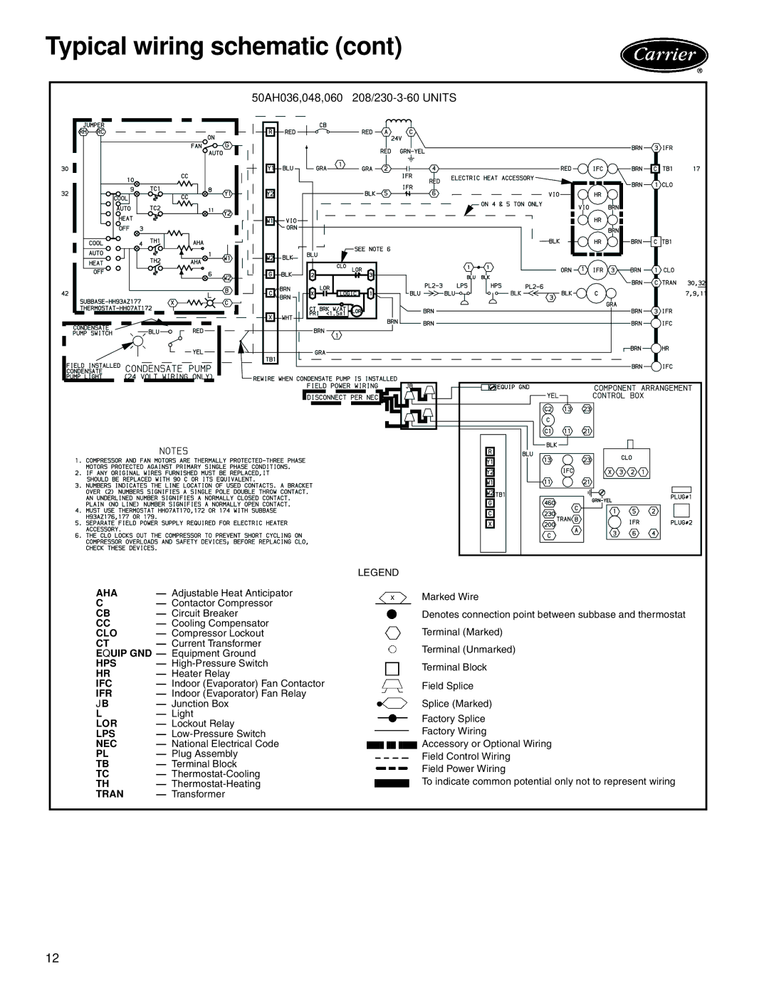
| 50AH036,048,060 — | ||
|
| LEGEND | |
AHA | — Adjustable Heat Anticipator | Marked Wire | |
C | — Contactor Compressor | ||
| |||
CB | — Circuit Breaker | Denotes connection point between subbase and thermostat | |
CC | — Cooling Compensator | Terminal (Marked) | |
CLO | — Compressor Lockout | ||
CT | — Current Transformer | Terminal (Unmarked) | |
EQUIP GND — Equipment Ground | |||
| |||
HPS | — | Terminal Block | |
HR | — Heater Relay | ||
| |||
IFC | — Indoor (Evaporator) Fan Contactor | Field Splice | |
IFR | — Indoor (Evaporator) Fan Relay |
| |
JB | — Junction Box | Splice (Marked) | |
L | — Light | Factory Splice | |
LOR | — Lockout Relay | ||
Factory Wiring | |||
LPS | — | ||
NEC | — National Electrical Code | Accessory or Optional Wiring | |
PL | — Plug Assembly | Field Control Wiring | |
TB | — Terminal Block | Field Power Wiring | |
TC | — | ||
To indicate common potential only not to represent wiring | |||
TH | — | ||
TRAN | — Transformer |
| |
12 |
|
| |