C99097

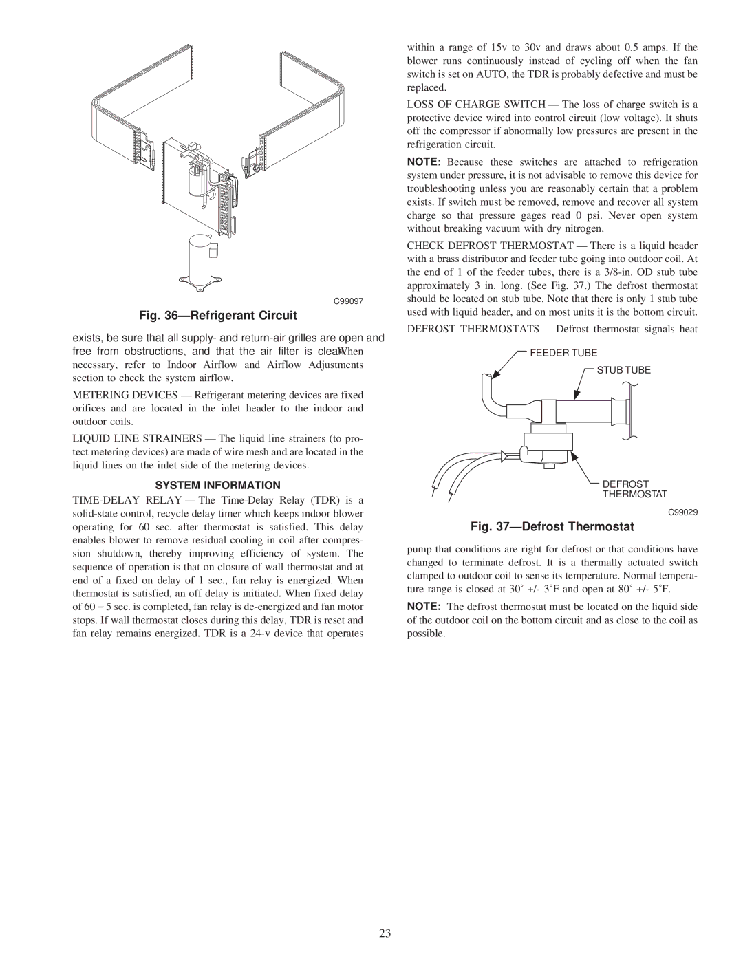
Fig. 36ÐRefrigerant Circuit

exists, be sure that all supply- and return-air grilles are open and free from obstructions, and that the air filter is clean. When necessary, refer to Indoor Airflow and Airflow Adjustments section to check the system airflow.

METERING DEVICES Ð Refrigerant metering devices are fixed orifices and are located in the inlet header to the indoor and outdoor coils.

LIQUID LINE STRAINERS Ð The liquid line strainers (to pro- tect metering devices) are made of wire mesh and are located in the liquid lines on the inlet side of the metering devices.

SYSTEM INFORMATION

TIME-DELAY RELAY Ð The Time-Delay Relay (TDR) is a solid-state control, recycle delay timer which keeps indoor blower operating for 60 sec. after thermostat is satisfied. This delay enables blower to remove residual cooling in coil after compres- sion shutdown, thereby improving efficiency of system. The sequence of operation is that on closure of wall thermostat and at end of a fixed on delay of 1 sec., fan relay is energized. When thermostat is satisfied, an off delay is initiated. When fixed delay of 60 ± 5 sec. is completed, fan relay is de-energized and fan motor stops. If wall thermostat closes during this delay, TDR is reset and fan relay remains energized. TDR is a 24-v device that operates

within a range of 15v to 30v and draws about 0.5 amps. If the blower runs continuously instead of cycling off when the fan switch is set on AUTO, the TDR is probably defective and must be replaced.

LOSS OF CHARGE SWITCH Ð The loss of charge switch is a protective device wired into control circuit (low voltage). It shuts off the compressor if abnormally low pressures are present in the refrigeration circuit.

NOTE: Because these switches are attached to refrigeration system under pressure, it is not advisable to remove this device for troubleshooting unless you are reasonably certain that a problem exists. If switch must be removed, remove and recover all system charge so that pressure gages read 0 psi. Never open system without breaking vacuum with dry nitrogen.

CHECK DEFROST THERMOSTAT Ð There is a liquid header with a brass distributor and feeder tube going into outdoor coil. At the end of 1 of the feeder tubes, there is a 3/8-in. OD stub tube approximately 3 in. long. (See Fig. 37.) The defrost thermostat should be located on stub tube. Note that there is only 1 stub tube used with liquid header, and on most units it is the bottom circuit.

DEFROST THERMOSTATS Ð Defrost thermostat signals heat

FEEDER TUBE

STUB TUBE

DEFROST

THERMOSTAT

C99029

Fig. 37ÐDefrost Thermostat

pump that conditions are right for defrost or that conditions have changed to terminate defrost. It is a thermally actuated switch clamped to outdoor coil to sense its temperature. Normal tempera- ture range is closed at 30Ê +/- 3ÊF and open at 80Ê +/- 5ÊF.

NOTE: The defrost thermostat must be located on the liquid side of the outdoor coil on the bottom circuit and as close to the coil as possible.

23

Page 23
Image 23
Carrier 50JS instruction manual System Information, C99097, C99029

50JS specifications

The Carrier 50JS is a high-performance rooftop unit designed for commercial applications, combining advanced technology with energy efficiency to deliver optimal heating and cooling performance. Its compact design allows for easy installation, making it an ideal choice for various settings such as retail spaces, schools, and office buildings.

One of the standout features of the Carrier 50JS is its innovative energy efficiency. Equipped with a high-efficiency scroll compressor, it significantly reduces energy consumption while providing reliable climate control. This model boasts a commendable SEER (Seasonal Energy Efficiency Ratio) rating, which translates to lower utility bills and a reduced carbon footprint, meeting modern energy efficiency standards.

The 50JS unit utilizes R-410A refrigerant, an environmentally friendly option that contributes to its low global warming potential compared to traditional refrigerants. This aligns with Carrier's commitment to sustainability and reducing environmental impact.

Another significant characteristic of the 50JS is its advanced controls and intelligent building integration capabilities. The unit comes with a microprocessor-based control system that allows for precise temperature management and can be easily integrated into building automation systems. This feature enhances user experience, providing real-time data and better management of HVAC operations.

Noise reduction technology is also a key design focus of the Carrier 50JS. The unit incorporates sound-attenuating materials and features that minimize operational noise, making it suitable for noise-sensitive environments like offices and educational institutions.

In terms of air quality, the 50JS offers various filtration options, including high-efficiency filters that remove airborne particulates. This results in cleaner, healthier indoor air, which is crucial for occupant comfort and well-being.

Furthermore, the rooftop unit is built to withstand harsh weather conditions, featuring a durable cabinet constructed from galvanized steel with a corrosion-resistant finish. This enhances the unit's longevity and reliability over time.

In conclusion, the Carrier 50JS rooftop unit stands out in the commercial HVAC market due to its energy efficiency, advanced controls, quiet operation, and robust design. It represents a blend of state-of-the-art technology and practical features, making it a preferred choice for those looking to invest in reliable and sustainable climate control solutions.