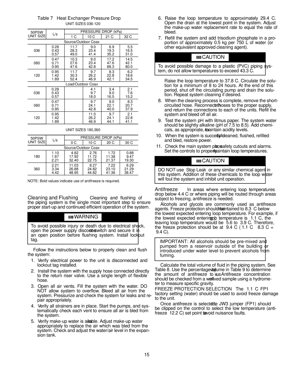
Table 7 — Heat Exchanger Pressure Drop

UNIT SIZES 036-120

50PSW

L/s


PRESSURE DROP (kPa)


UNIT SIZE

–1 C


10 C


21 C


32 C


Source/Outdoor Coax


036

0.28

11.7


9.0


6.9


5.5

0.43

28.3


23.4


19.3


16.5


0.57

49.0


41.4


35.2


31.0

060

0.47

10.3


9.0


17.2


14.5

0.71

27.6


23.4


47.6


42.1


0.95

47.6


42.8


88.3


80.0

120

0.95

11.7


9.7


8.3


6.2

1.42

30.3


26.2


22.8


18.6


1.89

52.4


46.9


42.1


34.5


Load/Outdoor Coax


036

0.28


4.1


3.4


2.1

0.43


9.7


9.0


7.6


0.57


18.0


16.5


15.2

060

0.47


9.7


9.0


8.3

0.71


24.1


22.1


20.7


0.95


42.8


40.0


37.9

120

0.95


11.0


9.7


2.1

1.42


26.2


24.1


22.8


1.89


46.9


44.1


41.1


UNIT SIZES 180,360


50PSW

L/s


PRESSURE DROP (kPa)


UNIT SIZE

0 C


10 C


20 C


30 C


Source/Outdoor Coax


180

1.10

4.82


2.76


1.72


0.88

1.67

17.92


11.72


11.38


9.47


2.21

32.40


22.75


21.37


19.30

360

2.21

11.03


8.27


7.22


6.29

3.34

26.88


24.82


23.10


21.29


4.42

48.95


44.82


41.36


38.47

NOTE: Bold values indicate use of antifreeze is required.

Cleaning and Flushing — Cleaning and flushing of the piping system is the single most important step to ensure proper start-up and continued efficient operation of the system.

WARNING

To avoid possible injury or death due to electrical shock, open the power supply disconnect switch and secure it in an open position before flushing system. Install lockout tag.

Follow the instructions below to properly clean and flush the system:

1.Verify electrical power to the unit is disconnected and lockout tag installed.

2.Install the system with the supply hose connected directly to the return riser valve. Use a single length of flexible hose.

3.Open all air vents. Fill the system with the water. DO NOT allow system to overflow. Bleed all air from the system. Pressurize and check the system for leaks and re- pair appropriately.

4.Verify all strainers are in place. Start the pumps, and sys- tematically check each vent to ensure all air is bled from the system.

5.Verify make-up water is available. Adjust make-up water appropriately to replace the air which was bled from the system. Check and adjust the water/air level in the expan- sion tank.

6.Raise the loop temperature to approximately 29.4 C. Open the drain at the lowest point in the system. Adjust the make-up water replacement rate to equal the rate of bleed.

7.Refill the system and add trisodium phosphate in a pro- portion of approximately 0.5 kg per 750 L of water (or other equivalent approved cleaning agent).

CAUTION

To avoid possible damage to a plastic (PVC) piping sys- tem, do not allow temperatures to exceed 43.3 C.

Raise the loop temperature to 37.8 C. Circulate the solu- tion for a minimum of 8 to 24 hours. At the end of this period, shut off the circulating pump and drain the solu- tion. Repeat system cleaning if desired.

8.When the cleaning process is complete, remove the short- circuited hose. Reconnect the hoses to the proper supply, and return the connections to each of the units. Refill the system and bleed off all air.

9.Test the system pH with litmus paper. The system water should be slightly alkaline (pH of 7.5 to 8.5). Add chemi- cals, as appropriate, to maintain acidity levels.

10.When the system is successfully cleaned, flushed, refilled and bled, restore power.

11.Check the main system panels, safety cutouts and alarms. Set the controls to properly maintain loop temperatures.

CAUTION

DO NOT use “Stop Leak” or any similar chemical agent in this system. Addition of these chemicals to the loop water will foul the system and inhibit unit operation.

Antifreeze — In areas where entering loop temperatures drop below 4.4 C or where piping will be routed through areas subject to freezing, antifreeze is needed.

Alcohols and glycols are commonly used as antifreeze agents. Freeze protection should be maintained to 8.3° C below the lowest expected entering loop temperature. For example, if the lowest expected entering loop temperature is –1.1 C, the leaving loop temperature would be –5.6 to –3.9 C. Therefore, the freeze protection should be at –9.4 C (–1.1 C – 8.3 C = –9.4 C).

IMPORTANT: All alcohols should be pre-mixed and pumped from a reservoir outside of the building or introduced under water level to prevent alcohols from fuming.

Calculate the total volume of fluid in the piping system. See Table 8. Use the percentage by volume in Table 9 to determine the amount of antifreeze to use. Antifreeze concentration should be checked from a well mixed sample using a hydrome- ter to measure specific gravity.

FREEZE PROTECTION SELECTION — The –1.1 C FP1 factory setting (water) should be used to avoid freeze damage to the unit.

Once antifreeze is selected, the JW3 jumper (FP1) should be clipped on the control to select the low temperature (anti- freeze –12.2 C) set point to avoid nuisance faults.

15

Page 15
Image 15
Carrier 50PSW036-360 specifications Heat Exchanger Pressure Drop, Unit Size

50PSW036-360 specifications

The Carrier 50PSW036-360 is a highly efficient and reliable rooftop unit designed for commercial applications. It combines advanced technologies and innovative features to provide optimal indoor comfort while ensuring energy savings and ease of operation. Its robust construction and numerous functionalities make the 50PSW036-360 an ideal choice for various building types, from retail spaces to office complexes.

One of the main features of the Carrier 50PSW036-360 is its efficient cooling and heating capabilities. It employs state-of-the-art scroll compressors, which deliver consistent performance and lower noise levels while consuming less energy compared to conventional compressors. This translates into significant energy savings, making it a cost-effective solution for businesses aiming to reduce their operational expenses.

The unit is equipped with a range of advanced technologies, including Carrier’s EcoBlue™ technology, which optimizes airflow and enhances energy efficiency. This technology helps achieve higher SEER (Seasonal Energy Efficiency Ratio) ratings, allowing users to benefit from lower utility bills without sacrificing comfort. Additionally, the unit comes with smart control options, enabling users to easily manage and monitor temperature settings, fan speeds, and energy consumption through intuitive interfaces.

The Carrier 50PSW036-360 also emphasizes versatility and adaptability. It has a compact design that makes it easy to install on rooftops, while its extensive selection of options, such as electric heat and economizers, allows it to be configured to meet various application requirements. Its advanced filtration system ensures high indoor air quality by removing dust, allergens, and other pollutants, which is essential for maintaining a healthy indoor environment.

Durability is another characteristic that sets the Carrier 50PSW036-360 apart. The unit is constructed using high-quality materials designed to withstand the rigors of outdoor environments. This ensures longevity and reliability, making it an excellent long-term investment for businesses.

In summary, the Carrier 50PSW036-360 is a top-of-the-line rooftop unit, ideal for commercial applications. Its blend of energy efficiency, advanced technologies, and robust construction makes it a preferred choice for maintaining optimal indoor climate conditions. With its versatility, durability, and ease of use, this system ensures comfort for occupants while helping businesses achieve their sustainability goals.