Table 8 — Approximate Fluid Volume (L)

per 30 M of Pipe

PIPE

DIAMETER (in.) [mm]

VOLUME (gal.) [L]

Copper

1

[25.4]

4.1

[15.5]


1.25 [31.8]

6.4

[24.2]


1.5 [38.1]

9.2

[34.8]

Rubber Hose

1

[25.4]

3.9

[14.8]

Polyethylene

3/4 IPS SDR11

2.8

[10.6]


1

IPS SDR11

4.5

[17.0]


11/4 IPS SDR11

8.0

[30.8]


1/2 IPS SDR11

10.9

[41.3]


2

IPS SDR11

18.0

[68.1]


11/4 IPS SCH40

8.3

[31.4]


11/2 IPS SCH40

10.9

[41.3]


2

IPS SCH40

17.0

[64.4]

LEGEND

IPS — Internal Pipe Size

SCH — Schedule

SDR — Standard Dimensional Ratio

NOTE: Volume of heat exchanger is approximately 1.0 gallon (3.78 liters).

Table 9 — Antifreeze Percentages by Volume


MINIMUM TEMPERATURE FOR FREEZE

ANTIFREEZE


PROTECTION (C)


–12.2

–9.4

–6.7

–3.9

Methanol (%)

25

21

16

10

100% USP Food Grade

38

30

22

15

Propylene Glycol (%)


Ethanol (%)

29

25

20

14

Cooling Tower/Boiler Systems — These systems typically use a common loop maintained at 15.6 to 32.2 C. The use of a closed circuit evaporative cooling tower with a second- ary heat exchanger between the tower and the water loop is rec- ommended. If an open type cooling tower is used continuously, chemical treatment and filtering will be necessary.

Ground Coupled, Closed Loop and Plateframe Heat Exchanger Well Systems — These systems al- low water temperatures from –1.1 to 43.3 C. The external loop field is divided up into 51 mm polyethylene supply and return lines. Each line has valves connected in such a way that upon system start-up, each line can be isolated for flushing using only the system pumps. Air separation should be located in the pip- ing system prior to the fluid re-entering the loop field.

OPERATION

Power Up Mode — The unit will not operate until all the inputs, terminals and safety controls are checked for normal operation.

NOTE: The compressor will have a 5-minute anti-short cycle upon power up.

Units with Aquazone™ Complete C Control

NOTE: On all subsequent compressor calls the random start delay is omitted.

HEATING STAGE 2 — To enter Stage 2 mode, terminal W is active (Y is already active). Also, the G terminal must be active or the W terminal is disregarded.

Units with Aquazone Deluxe D Control

STANDBY — The compressor will be off. The reversing valve (RV) relays will be on if inputs are present.

HEATING STAGE 1 — In Heating Stage 1 mode, the fan en- able and compressor relays are turned on immediately. Once the demand is removed, the relays are turned off and the con- trol reverts to standby mode. If there is a master/slave or dual compressor application, all compressor relays and related func- tions will operate per their associated DIP switch 2 setting on S1.

HEATING STAGE 2 — In Heating Stage 2 mode, the com- pressor relays remain on. The control reverts to Heating Stage 1 mode once demand is removed. If there is a master/slave or dual compressor application, all compressor relays and related functions will operate per their associated DIP switch 2 setting on S1.

COOLING STAGE 1 — In Cooling Stage 1 mode, the com- pressor and RV relays are turned on immediately. If configured as stage 2 (DIP switch set to OFF) then the compressor and fan will not turn on until there is a stage 2 demand. The compressor relays are turned off immediately when the Cooling Stage 1 de- mand is removed. The control reverts to standby mode. The RV relay remains on until there is a heating demand. If there is a master/slave or dual compressor application, all compressor relays and related functions will track with their associated DIP switch 2 on S1.

COOLING STAGE 2 — In Cooling Stage 2 mode, the com- pressor and RV relays remain on. The control reverts to Cool- ing Stage 1 mode once the demand is removed. If there is a master/slave or dual compressor application, all compressor re- lays and related functions will track with their associated DIP switch 2 on S1.

NIGHT LOW LIMIT (NLL) STAGED HEATING — In NLL staged heating mode, the override (OVR) input becomes active and is recognized as a call for heating and the control will immediately go into a Heating Stage 1 mode. With an additional 30 minutes of NLL demand, the control will go into Heating Stage 2 mode. With another additional 30 minutes of NLL demand, the control will go into Heating Stage 3 mode.

SYSTEM TEST

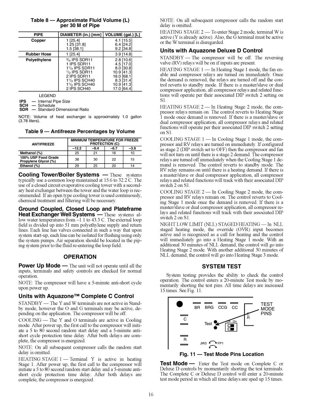
System testing provides the ability to check the control operation. The control enters a 20-minute Test mode by mo- mentarily shorting the test pins. All time delays are increased 15 times. See Fig. 11.

STANDBY — The Y and W terminals are not active in Stand- by mode, however the O and G terminals may be active, de- pending on the application. The compressor will be off.

COOLING — The Y and O terminals are active in Cooling mode. After power up, the first call to the compressor will initi- ate a 5 to 80 second random start delay and a 5-minute anti- short cycle protection time delay. After both delays are com- plete, the compressor is energized.

NOTE: On all subsequent compressor calls the random start delay is omitted.

BR BRG

CCG

CC

C

Off

On

Test


R


JW3

FP1


TEST

MODE

CPINS

R

HEATING STAGE 1 — Terminal Y is active in heating Stage 1. After power up, the first call to the compressor will initiate a 5 to 80 second random start delay and a 5-minute anti- short cycle protection time delay. After both delays are complete, the compressor is energized.

Fig. 11 — Test Mode Pins Location

Test Mode — Enter the Test mode on Complete C or Deluxe D controls by momentarily shorting the test terminals. The Complete C or Deluxe D control will enter a 20-minute test mode period in which all time delays are sped up 15 times.

16

Page 16
Image 16
Carrier 50PSW036-360 Operation, Units with Aquazone Complete C Control, Units with Aquazone Deluxe D Control, System Test

50PSW036-360 specifications

The Carrier 50PSW036-360 is a highly efficient and reliable rooftop unit designed for commercial applications. It combines advanced technologies and innovative features to provide optimal indoor comfort while ensuring energy savings and ease of operation. Its robust construction and numerous functionalities make the 50PSW036-360 an ideal choice for various building types, from retail spaces to office complexes.

One of the main features of the Carrier 50PSW036-360 is its efficient cooling and heating capabilities. It employs state-of-the-art scroll compressors, which deliver consistent performance and lower noise levels while consuming less energy compared to conventional compressors. This translates into significant energy savings, making it a cost-effective solution for businesses aiming to reduce their operational expenses.

The unit is equipped with a range of advanced technologies, including Carrier’s EcoBlue™ technology, which optimizes airflow and enhances energy efficiency. This technology helps achieve higher SEER (Seasonal Energy Efficiency Ratio) ratings, allowing users to benefit from lower utility bills without sacrificing comfort. Additionally, the unit comes with smart control options, enabling users to easily manage and monitor temperature settings, fan speeds, and energy consumption through intuitive interfaces.

The Carrier 50PSW036-360 also emphasizes versatility and adaptability. It has a compact design that makes it easy to install on rooftops, while its extensive selection of options, such as electric heat and economizers, allows it to be configured to meet various application requirements. Its advanced filtration system ensures high indoor air quality by removing dust, allergens, and other pollutants, which is essential for maintaining a healthy indoor environment.

Durability is another characteristic that sets the Carrier 50PSW036-360 apart. The unit is constructed using high-quality materials designed to withstand the rigors of outdoor environments. This ensures longevity and reliability, making it an excellent long-term investment for businesses.

In summary, the Carrier 50PSW036-360 is a top-of-the-line rooftop unit, ideal for commercial applications. Its blend of energy efficiency, advanced technologies, and robust construction makes it a preferred choice for maintaining optimal indoor climate conditions. With its versatility, durability, and ease of use, this system ensures comfort for occupants while helping businesses achieve their sustainability goals.