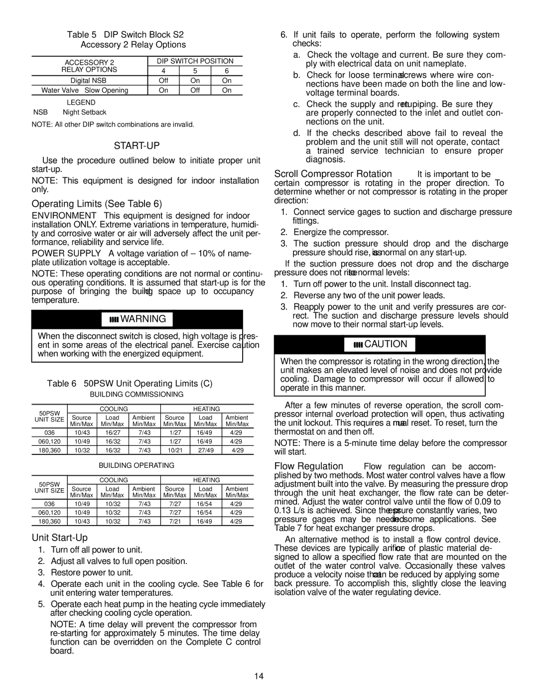
Table 5 — DIP Switch Block S2 —

Accessory 2 Relay Options

ACCESSORY 2

DIP SWITCH POSITION

RELAY OPTIONS

4

5

6

Digital NSB

Off

On

On

Water Valve — Slow Opening

On

Off

On

LEGEND


NSB — Night Setback

NOTE: All other DIP switch combinations are invalid.

START-UP

Use the procedure outlined below to initiate proper unit start-up.

NOTE: This equipment is designed for indoor installation only.

Operating Limits (See Table 6)

ENVIRONMENT — This equipment is designed for indoor installation ONLY. Extreme variations in temperature, humidi- ty and corrosive water or air will adversely affect the unit per- formance, reliability and service life.

POWER SUPPLY — A voltage variation of ± 10% of name- plate utilization voltage is acceptable.

NOTE: These operating conditions are not normal or continu- ous operating conditions. It is assumed that start-up is for the purpose of bringing the building space up to occupancy temperature.

WARNING

When the disconnect switch is closed, high voltage is pres- ent in some areas of the electrical panel. Exercise caution when working with the energized equipment.

Table 6 — 50PSW Unit Operating Limits (C)

BUILDING COMMISSIONING

50PSW


COOLING


HEATING


UNIT SIZE

Source

Load

Ambient

Source

Load

Ambient


Min/Max

Min/Max

Min/Max

Min/Max

Min/Max

Min/Max

036

10/43

16/27

7/43

–1/27

16/49

4/29

060,120

10/49

16/32

7/43

–1/27

16/49

4/29

180,360

10/32

16/32

7/43

10/21

27/49

4/29

BUILDING OPERATING

50PSW


COOLING


HEATING


UNIT SIZE

Source

Load

Ambient

Source

Load

Ambient

Min/Max

Min/Max

Min/Max

Min/Max

Min/Max

Min/Max

036

10/49

10/32

7/43

–7/27

16/54

4/29

060,120

10/49

10/32

7/43

–7/27

16/54

4/29

180,360

10/43

10/32

7/43

–7/21

16/49

4/29

Unit Start-Up

1.Turn off all power to unit.

2.Adjust all valves to full open position.

3.Restore power to unit.

4.Operate each unit in the cooling cycle. See Table 6 for unit entering water temperatures.

5.Operate each heat pump in the heating cycle immediately after checking cooling cycle operation.

NOTE: A time delay will prevent the compressor from re-starting for approximately 5 minutes. The time delay function can be overridden on the Complete C control board.

6.If unit fails to operate, perform the following system checks:

a.Check the voltage and current. Be sure they com- ply with electrical data on unit nameplate.

b.Check for loose terminal screws where wire con- nections have been made on both the line and low- voltage terminal boards.

c.Check the supply and return piping. Be sure they are properly connected to the inlet and outlet con- nections on the unit.

d.If the checks described above fail to reveal the problem and the unit still will not operate, contact a trained service technician to ensure proper diagnosis.

Scroll Compressor Rotation — It is important to be certain compressor is rotating in the proper direction. To determine whether or not compressor is rotating in the proper direction:

1.Connect service gages to suction and discharge pressure fittings.

2.Energize the compressor.

3.The suction pressure should drop and the discharge pressure should rise, as is normal on any start-up.

If the suction pressure does not drop and the discharge pressure does not rise to normal levels:

1.Turn off power to the unit. Install disconnect tag.

2.Reverse any two of the unit power leads.

3.Reapply power to the unit and verify pressures are cor- rect. The suction and discharge pressure levels should now move to their normal start-up levels.

CAUTION

When the compressor is rotating in the wrong direction, the unit makes an elevated level of noise and does not provide cooling. Damage to compressor will occur if allowed to operate in this manner.

After a few minutes of reverse operation, the scroll com- pressor internal overload protection will open, thus activating the unit lockout. This requires a manual reset. To reset, turn the thermostat on and then off.

NOTE: There is a 5-minute time delay before the compressor will start.

Flow Regulation — Flow regulation can be accom- plished by two methods. Most water control valves have a flow adjustment built into the valve. By measuring the pressure drop through the unit heat exchanger, the flow rate can be deter- mined. Adjust the water control valve until the flow of 0.09 to

0.13L/s is achieved. Since the pressure constantly varies, two pressure gages may be needed in some applications. See Table 7 for heat exchanger pressure drops.

An alternative method is to install a flow control device. These devices are typically an orifice of plastic material de- signed to allow a specified flow rate that are mounted on the outlet of the water control valve. Occasionally these valves produce a velocity noise that can be reduced by applying some back pressure. To accomplish this, slightly close the leaving isolation valve of the water regulating device.

14

Page 14
Image 14
Carrier 50PSW036-360 Operating Limits See Table, Unit Start-Up, DIP Switch Block S2 Accessory 2 Relay Options

50PSW036-360 specifications

The Carrier 50PSW036-360 is a highly efficient and reliable rooftop unit designed for commercial applications. It combines advanced technologies and innovative features to provide optimal indoor comfort while ensuring energy savings and ease of operation. Its robust construction and numerous functionalities make the 50PSW036-360 an ideal choice for various building types, from retail spaces to office complexes.

One of the main features of the Carrier 50PSW036-360 is its efficient cooling and heating capabilities. It employs state-of-the-art scroll compressors, which deliver consistent performance and lower noise levels while consuming less energy compared to conventional compressors. This translates into significant energy savings, making it a cost-effective solution for businesses aiming to reduce their operational expenses.

The unit is equipped with a range of advanced technologies, including Carrier’s EcoBlue™ technology, which optimizes airflow and enhances energy efficiency. This technology helps achieve higher SEER (Seasonal Energy Efficiency Ratio) ratings, allowing users to benefit from lower utility bills without sacrificing comfort. Additionally, the unit comes with smart control options, enabling users to easily manage and monitor temperature settings, fan speeds, and energy consumption through intuitive interfaces.

The Carrier 50PSW036-360 also emphasizes versatility and adaptability. It has a compact design that makes it easy to install on rooftops, while its extensive selection of options, such as electric heat and economizers, allows it to be configured to meet various application requirements. Its advanced filtration system ensures high indoor air quality by removing dust, allergens, and other pollutants, which is essential for maintaining a healthy indoor environment.

Durability is another characteristic that sets the Carrier 50PSW036-360 apart. The unit is constructed using high-quality materials designed to withstand the rigors of outdoor environments. This ensures longevity and reliability, making it an excellent long-term investment for businesses.

In summary, the Carrier 50PSW036-360 is a top-of-the-line rooftop unit, ideal for commercial applications. Its blend of energy efficiency, advanced technologies, and robust construction makes it a preferred choice for maintaining optimal indoor climate conditions. With its versatility, durability, and ease of use, this system ensures comfort for occupants while helping businesses achieve their sustainability goals.