Manuals
/
Carrier
/
Computer Equipment
/
Computer Drive
Carrier
D2-3466-2
instruction manual
Initial DC Bus
Models:
D2-3466-2
1
21
38
38
Download
38 pages
49.13 Kb
18
19
20
21
22
23
24
25
Error messages
Input Ground Fault Excessive
Resetting a Checksum CHS Fault
Monitor Mode
Page 21
Image 21
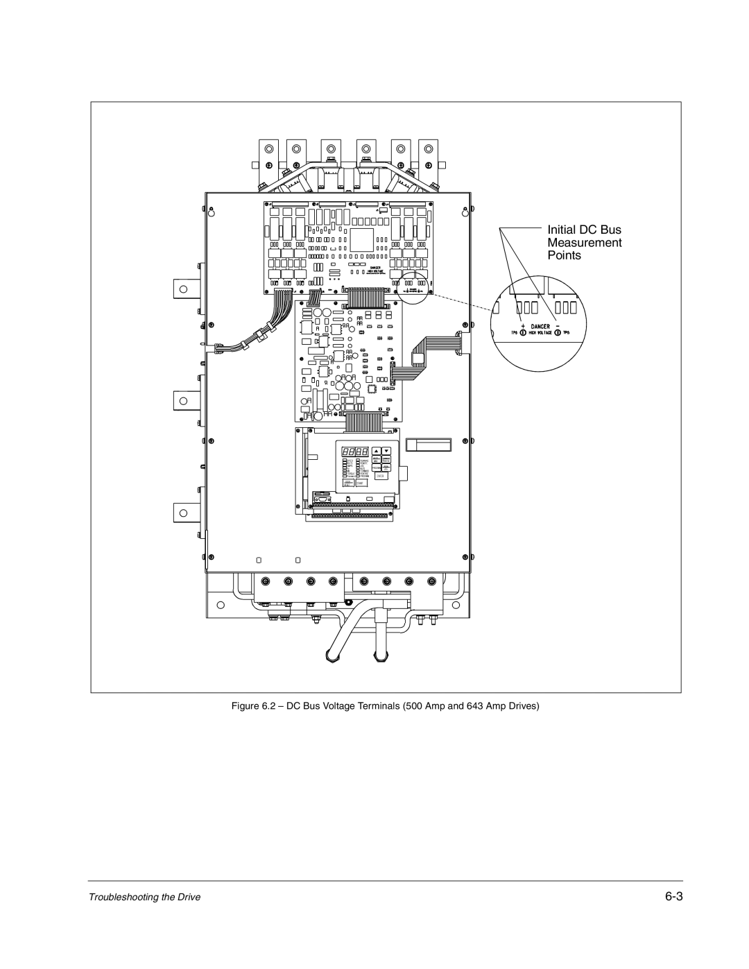
Initial DC Bus
Measurement
Points
Figure 6.2 – DC Bus Voltage Terminals (500 Amp and 643 Amp Drives)
Troubleshooting the Drive
6-3
Page 20
Page 22
Page 21
Image 21
Page 20
Page 22
Contents
Carrier VFD Quick Reference
Page
Page
Page
Page
Page
Contents
Carrier VFD Quick Reference
Getting Assistance from Reliance Electric
Required Publications
Carrier VFD Quick Reference
Replace with 2.fm 11 X 17 Z-fold
Carrier VFD Quick Reference
Monitor Mode
Carrier VFD Quick Reference
For Carrier Drives
Carrier VFD Quick Reference
Record the following nameplate information
Record the following job information
Carrier VFD Quick Reference
Verifying That DC Bus Capacitors Are Discharged
Test Equipment Needed To Troubleshoot
POS NEG TP1 TP2
Initial DC Bus
Checking the Power Modules and Motor with Input Power Off
Igbt
Alarm Codes
Troubleshooting the Drive Using Error Codes
Fault Codes
Error Log
Alarm Code Description Alarm Cause Corrective Action
Identifying Alarm Codes and Recovering
Fault Code Description Fault Cause Corrective Action
Identifying Fault Codes and Recovering
IPL
OPL
Input Ground Fault Excessive
Asymmetrical Bus When
Slow Ramp Rate of DC Bus DC
Carrier VFD Quick Reference
Troubleshooting the Drive
Code Fault Description Fault Cause Corrective Action
Identifying Fatal Fault Codes and Recovering
Indentifying PMC Board Fault Codes and Recovering
Resetting a Checksum CHS Fault
Status of LEDs Fault Description Corrective Action
Model Amps Code Number
Technical Writing Internal Use
DIF
Page
Page
Publication D2-3466-2 May 2005 -- Supercedes D2-3466-1 June
Top
Page
Image
Contents