Contents
Contents
Service Technician Guide
Summary of DANGERS, WARNINGS, and Cautions
Introduction
Disconnect Power for CORD-CONNECTED Unit
Unit Disassembly
Disconnect Power for Permanently Connected Hardwired Units
Tools Needed
Remove the Unit from the Wall Sleeve
Open the Control BOX
Accessing INDOOR-AIR Section Components
Accessing Unit Components
Accessing OUTDOOR-AIR Section Components
Remove the Discharge Deck Assembly
Remove the AIR Discharge Grille
Ptac Unit with Lateral Duct Accessory Installed
Gusset Removal
Location of Screws on Discharge Grille
Reinstall Front Panel
Cleaning and Safety
General Cleaning
Component Cleaning Schedule
Cleaning the Outdoor AIR Vent Filter
Monthly Cleaning
Cleaning the Indoor and Outdoor Coils
Seasonal Cleaning
Access and Clean Indoor FAN and FAN Scroll
Ptac Exterior Surfaces
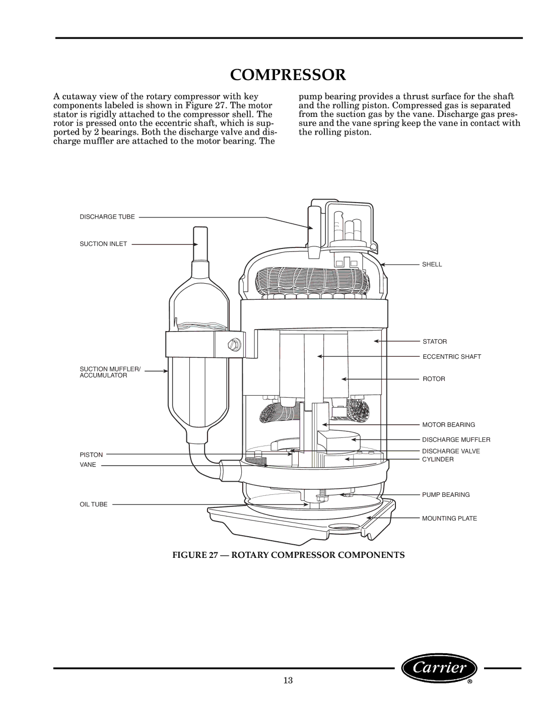
Rotary Compressor Components
Compressor
Disconnect ALL Power to the Unit
Compressor Troubleshooting
Basic Hermetic Compressor Electrical Measurements
Basic Compressor Troubleshooting Guide
Compressor Replacement
SHORTED/OPEN Windings Test
Strainer Capillary Tube Location
Common Causes Heater Failure
Heaters
Heater Removal
Acceptable Heater Resistance Values
Disconnect ALL Power to Unit
UNIT-MOUNTED Controls
Operating Controls
WALL-MOUNTED Thermostat Controls
Remote Thermostat Troubleshooting
Do not daisy chain R 24 VAC
NON-USER Adjustable Controls
Description of Selector Switch Settings Figure
Sequence of Operation
Component Operation and Troubleshooting
Tools Needed
Indoor Thermostat IT CONTACTS, ALL 52CE, PE Models
Indoor Thermostat IT CONTACTS, ALL 52CQ, PQ Models
Capacitor Test
Electrical Components Removal and Replacement
Component Locations Open Control BOX
FAN Motor
FAN Motor Troubleshooting
Basic FAN Motor Electrical Tests
Typical 265 Volt Motors
FAN Motor Troubleshooting Chart Typical 208/230 Volt Motors
Location of Wiring Schematic On Front Panel of Control BOX
FAN Motor Replacement
Field Temperature Charts
100 110 120 130
52P 12,000 BTU Unit Field Temperature Chart High Cool 50% RH
Indoor
Series
Indoor
52C,P Series
Page
000 Btu 52P-12,000 Btu 52C-12,000 Btu 15,000 Btu
Refer to Figures 68-72 for Typical Wiring Schematics
Wiring Diagrams
Component Legend
CAP
Component Connection Marked Fan Motor
Page
Most Frequent Ptac Service Questions
Accessory Form Number Part Number Description
Accessories
Amps
52C Performance and Physical Data
52PE-512---3
52P Performance and Physical Data
Page
Page
Copyright 2002 Carrier Corporation